planet10 said:
It is possible to separate the CT on these (at least the ones RS sells in Canada) to give 2 6.3V secondaries.
dave
Hi Dave-
The RS part number I found is 273-1511B. And now that I'm looking at the transformer it is a 6.3-0-6.3V transformer (3A) so I should be good to go.
I would use the 6.3-0 of the 269AX for the PSU tube (still not clear to me how to implement a center tap via the resistor arrangement Bas mentioned in an eariler post).
Could I use the RS transformer to feed 6.3 V to each of the tubes (6N1P and 5687) for BOTH channels by using a terminal strip to create two leads from each 6.3V secondary and four leads from the center tap?
Or I suppose I could use both RS transformers, one for each channel but that would seem to be overkill.
Thanks,
SteveA
SteveA said:The RS part number I found is 273-1511B. And now that I'm looking at the transformer it is a 6.3-0-6.3V transformer (3A) so I should be good to go.
That is the same part #. You'd be best to separate the centre tap and use one secondary for each channel.
Using the Hammond trafo filament 2ndary for the rectifier might be OK,,, i prefer to not have any of the filaments (certainly none of the filaments for signal carrying tubes) run off the B+ trafo.
dave
Hi Steve,
Depending were I look, the 269AX is shown with either 1 or 2 filament windings.
Why don’t you post the number and colors of all the wires you have…John
Depending were I look, the 269AX is shown with either 1 or 2 filament windings.
Why don’t you post the number and colors of all the wires you have…John
That is the same part #. You'd be best to separate the centre tap and use one secondary for each channel.
Dave-
What is meant by separating the center tap?
John
Depending were I look, the 269AX is shown with either 1 or 2 filament windings.
John-
The transformer markings are:
primaries (115) black-black
sec 1 red-red/yellow-red 250V (125-0-125, I assume)
sec 2 green-green 6.3V (both 6.3 or 6.3-0?)
Using the 269AX for the PSU the secondaries would go:
sec 1 the red's would go to the AC in pads and the center tap to ground (yes?)
sec 2 the green's would go to the filament pads for the rectifier tube (yes?)
Bas' manual indicates when using the 5687 tube in position 2 to provide separate voltage lines to the heater for tube 1. This would suggest to me I have four separate 6.3v lines to deal with. I can see a way to do it with two of the RS transformers.
Could I do it with one of them if I "separate" the center tap? And if so, how?
Thanks Dave, John, Bas
Steve
OK just one 6.3v sec. Use it for the rectifier tube (fil pads) and connect the two red leads to the AC pads.
In this case you do not use the CT ( red/yellow). Just tape it off well.
As for the other filaments. At this point, let’s drop the RS transformer and get a 6.3V CT. Hammond 166n6 will do nicely. Connect the CT(green/yellow) to the power supply PCB bias point.
The two green will feed all four signal tubes. The 6nip go to pins 4 & 5. For the 5687, one side goes to pin 8 the other to Both pins 4 & 5.
I did not use the 5687 in my Aikido so I don’t know how folks arranged there wiring off hand, but I will try to post something a bit later…John
As for the other filaments. At this point, let’s drop the RS transformer and get a 6.3V CT. Hammond 166n6 will do nicely. Connect the CT(green/yellow) to the power supply PCB bias point.
John-
The power supply PCB bias point being the pad labeled heater bias.
Assuming your diagram is correct, could I take each green lead to a terminal strip and have two leads coming out (basically making four leads) and then take them pairwise to each channel.
BTW, the RS transformer is a 6.3V CT transformer.
SteveA
The power supply PCB bias point being the pad labeled heater bias.
Yep.
Assuming your diagram is correct, could I take each green lead to a terminal strip and have two leads coming out (basically making four leads) and then take them pairwise to each channel.
Yes, assuming.
this was ment to give you a idea of how to wire and what points might be used. Other 5687 users might have a better idea.
In any case make sure that you twist the filament leads as tight as you can, to reduce hum.
What you need to do is, download the tube data sheets and verify that the heater pins are were I said they are (trust but verify)
Now take a sheet of paper and draw what you know
Perfect! That is how it should be wired.Maybe Bas would be kind enough to check...John
Yup!Assuming your diagram is correct, could I take each green lead to a terminal strip and have two leads coming out (basically making four leads) and then take them pairwise to each channel.
Great...just like mine. Thus you should connect the center tap to the bias point on the psu.BTW, the RS transformer is a 6.3V CT transformer.
Bas, John-
Many thanks, I should be able to handle it now. I'll report back after I get a listen to it.
Thanks again and Happy Holidays
SteveA
Many thanks, I should be able to handle it now. I'll report back after I get a listen to it.
Thanks again and Happy Holidays
SteveA
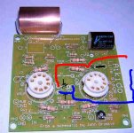
Example of wiring the boards with a Hammon 369JX transformer
 Compromised URL removed by Moderation
only one channel shown wired...
Compromised URL removed by Moderationonly one channel shown wired...
Last edited by a moderator:
Aikido voltages not equal
Well, my Aikido is hot. The TubeCad blog0011 schematic. 6N1P into 5687. PSU voltages are B+ at 218 at the anode (pin 1) on the first (upper) triode on each tube. But, here are my voltages at the reference points:
6n1p upper triode cathode - Left channel 109, right 146 - should be 111.4
6n1p lower triode anode - Left channel 108, right 144 - should be 110.
6n1p lower triode cathode- Left channel 1.3, right 4.3 - should be 1.2.
5687 lower triode anode - Left channel 108, right 138 - should be 110.
What could be the cause?
Also wondering about series connection of the 6n1p heaters on my 12V supply the first measures 12V, the second 6V. Is that normal?
Any help would be appreciated. This late in the day, my reasoning is getting weak.
Maynard
Attachments
Meunard
The first tube seems to be close to the average of the 6N1P, the second one seems to be much more far away (don't forget the given voltages are the result of Pspice calculation with perfectly matched tubes... welcome in the real world🙄 )
Are the tubes already burned in?
jacques
The first tube seems to be close to the average of the 6N1P, the second one seems to be much more far away (don't forget the given voltages are the result of Pspice calculation with perfectly matched tubes... welcome in the real world🙄 )
Are the tubes already burned in?
jacques
Feeling seriously foolish.
I guess a cathode resistor off by a factor of 34 would be enough to muck up the loadings on the tube. Out with the 15K, in with the 430R. My apologies.
MG
I guess a cathode resistor off by a factor of 34 would be enough to muck up the loadings on the tube. Out with the 15K, in with the 430R. My apologies.
MG
Anyone come up with an idea of how to make a good octal to noval adapter so we can use octal tubes in the Aikido?
Up to now I am very enthusiastic with the sound of the this pre.It beat my cutting edge opamp based pre quite easily in terms of musicality and transparency.However I did notice on occasion some motorboating with the woofers being slowly sucked in and out very slowly.This actually led to blowing up the chip of a tripath amp I had connected at the time when I tried to switch off the pre.
Right now it is still on an open style woodboard until I finish tweaking it.I did find that .47uf coupling caps were a bit on the thin side when driving my Alephx.I switched to 1.8uf and the bass was much better.
I am using 6h30 in both positions.Great tube.I discovered some 12ax7 nos I had were fried after a friend tried them in the place some 5687 in his amp by mistake.Initially I did not think this may have happened but the pin out switch is very dangerous between ax7 and 5687 because it applies the plate voltage to the heater midpoint and burns up the heater.
I have the suspicion the grid leak resistor may be a bit low to suppress oscillations in the 6h30.
I have the suspicion the grid leak resistor may be a bit low to suppress oscillations in the 6h30.
Quote:
Anyone come up with an idea of how to make a good octal to noval adapter so we can use octal tubes in the Aikido?
How about wiring the octal socket and circuit board to some short leads?
Example
The 6N1P's pin 6, 7, 8 would be a 6SN7's 5,4,6 The 6N1P's 1,2,3, would equal a 6SN7's 2,1,3
A 5687's 9,7,6 would equal a 6SN7's 5,4,6 and a 5687's 1,2,3 would equal a 6SN7's 2,1,3
I could be mistaken but I haven't seen an adaptor out.
Aikido voltages not equal Post #473
Well, my Aikido is hot. The TubeCad blog0011 schematic. 6N1P into 5687. PSU voltages are B+ at 218 at the anode (pin 1) on the first (upper) triode on each tube. But, here are my voltages at the reference points:
6n1p upper triode cathode - Left channel 109, right 146 - should be 111.4
6n1p lower triode anode - Left channel 108, right 144 - should be 110.
6n1p lower triode cathode- Left channel 1.3, right 4.3 - should be 1.2.
5687 lower triode anode - Left channel 108, right 138 - should be 110.
What could be the cause?
Also wondering about series connection of the 6n1p heaters on my 12V supply the first measures 12V, the second 6V. Is that normal?
Any help would be appreciated. This late in the day, my reasoning is getting weak.
Maynard
According to the circuit board I have pasted the resistor numbers in order to make it easier to track.
Attachments

- Home
- Amplifiers
- Tubes / Valves
- Poll..anyone interested in an Aikido linestage PCB group buy?