Thanks Bas,
I appreciate all the effort you have invested in these boards for us.
My question about PSUDII was on how to model the PS. Not if someone would do it for me. sorry if I was unclear on that.
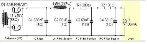
Here is what I have so far...
What other filter sections should I insert to model your Aikido PS board?
Thanks Bas,
Ron
I appreciate all the effort you have invested in these boards for us.
My question about PSUDII was on how to model the PS. Not if someone would do it for me. sorry if I was unclear on that.
Here is what I have so far...
What other filter sections should I insert to model your Aikido PS board?
Thanks Bas,
Ron
Attachments
Sorry, reread this thread and found my answer on page 9.
New question though.
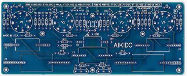
Using John Broskie's Aikido octal board which has ONE B+ input and one ground.
This power supply board has 2 B+ outputs, Left and Right B+.
The traces are from the positive side of C4 and C5, same ground.
Do I connect ONE or Both to the B+ input on JB's Aikido PCB?
Sorry if this has been coverd here, but I've read this thread and could have missed it.
Thanks
Ron
New question though.
Using John Broskie's Aikido octal board which has ONE B+ input and one ground.
This power supply board has 2 B+ outputs, Left and Right B+.
The traces are from the positive side of C4 and C5, same ground.
Do I connect ONE or Both to the B+ input on JB's Aikido PCB?
Sorry if this has been coverd here, but I've read this thread and could have missed it.
Thanks
Ron
Attachments
Bas had designed power supply for using with two mono boards.
http://glass-ware.stores.yahoo.net/mono9pin.html
http://glass-ware.stores.yahoo.net/mono9pin.html
JPS said:Bas had designed power supply for using with two mono boards.
http://glass-ware.stores.yahoo.net/mono9pin.html
Yes, thanks for that......I realize it has 2 outputs for 2 mono boards.
I think he built it for his mono boards though.
John Broskie's first boards were stereo on ONE board, Hence, my question about using just one of outuputs on Bas' PS PCBs.
I figured it out that Mr. Bas' board should be able to supply enough mA from ONE side to power Broskie's stereo board. I'll let the forum know if it works.
Ron
(Sorry I asked)
Would one of Bas's PSU boards be sufficient to power, say, the Aikido 5687 stereo board?
Also, would the Aikido process the signal from my MM phono cartridge with enough gain without a separate phono stage?
Also, would the Aikido process the signal from my MM phono cartridge with enough gain without a separate phono stage?
Would one of Bas's PSU boards be sufficient to power, say, the Aikido 5687 stereo board?
Yes for stereo board just don't mount R2 and C4 on pcb and take B+ output from point marked (B+) L
regards
That depends on how much current that board uses. And in turn how much current your power transformer can supply. And also it depends on the wattage of your resistors (on the psu board).Would one of Bas's PSU boards be sufficient to power, say, the Aikido 5687 stereo board?
You need a seperate phone stage because a phono stage also provides equalisation that is essential for getting half decent sound. So in short the answer would be no. You cannot process the signal from your phono cartridge with the Aikido.Also, would the Aikido process the signal from my MM phono cartridge with enough gain without a separate phono stage?
JPS said:
Yes for stereo board just don't mount R2 and C4 on pcb and take B+ output from point marked (B+) L
regards
Being an admitted newb at everything electronics and often wrong, I'm going to disagree with you on which channel he should use for powering one of JB's boards.
Looking at Bas' PS board layout (followiing traces) if you use (and populate) the right channel it will also give you the heater bias needed. The left channel won't do that. Looks like you can leave out C5 and R3.
Please let me know if I'm looking at the board incorrectly.
As stated I'm an admitted newb to electronics but not mains voltage.
Ron
Hi Ron,
In fact it doesn't matter.
 Compromised URL removed by Moderation
In retrospect it would have been better to make the heater bias after one of the second RC networks (in theory in practise it hardly matters)(we all make mistakes 🙁). In that case one would have had to choose B+ L or B+R whatever "arm" the bias would have been connected to in that case.
In fact it doesn't matter.
Compromised URL removed by ModerationIn retrospect it would have been better to make the heater bias after one of the second RC networks (in theory in practise it hardly matters)(we all make mistakes 🙁). In that case one would have had to choose B+ L or B+R whatever "arm" the bias would have been connected to in that case.
Last edited by a moderator:
Thanks Bas,
Looking at your PS board (thank you!) I see that the junction of R4 (top of the heater bias network) connects between C2 and C3.
Agreed, the bias could have been after the last R/C network but ripple reduction here probably makes little differnence.
And either Right or Left B+ out works equally well.
Thanks for taking the time and teaching us newbs.
Hey, learning is FUN!
Ron
Bas Horneman said:
That depends on how much current that board uses. And in turn how much current your power transformer can supply. And also it depends on the wattage of your resistors (on the psu board).
You need a seperate phone stage because a phono stage also provides equalisation that is essential for getting half decent sound. So in short the answer would be no. You cannot process the signal from your phono cartridge with the Aikido.
OK,
lets make the following assumptions.
B+ I will be looking for is 250V - something like the Edcor XPWR009 120 60 Hz 275-0-275 175ma 6.3V, 4A 5V, 3A
Total plate current will be 42mA (2x12 + 2x9 - if my thinking is correct)
Attached are the data sheets of the tubes that are suggested for this particular board. I do not know how to determine what watt resistors I will need.


Sounds about right to me.42mA
With the wattage I meant the following. Take resistor R1 it will have to cope with all the current.
P=I*I*R
0.042A*0.042A*1000R (if you will be using a 1k resistor)
= 1.764W
In that case I would go for a 5W resistor to be on the safe side.
Bas Horneman said:
Sounds about right to me.
With the wattage I meant the following. Take resistor R1 it will have to cope with all the current.
P=I*I*R
0.042A*0.042A*1000R (if you will be using a 1k resistor)
= 1.764W
In that case I would go for a 5W resistor to be on the safe side.
Gotcha...that is what I was thinking but I did not want to assume anything as I am still quite the noob...
I have ordered one of your boards.
Thanks for the info.
Now I just need to get my PT sorted out. After looking at the schematic again it would seem that the PT does not need the 5V CT winding. As for the heater circuit, if I wanted it all in one PT, what is the optimal configuration? 6.3V CT or a 12.6V winding? From the data sheets I think I would want a 6.3VCT, no?
Thanks,
Carl
If you are using one of JB's Aikido stereo boards, he recommends using a 12.6V heater supply and changing jumpers on the board to series the valve heaters.
12.6V heater supply into JB's board jumpered to 6.3V is 1/2 the current of 6.3V supply. As I understand it, less current = less chance of generated hum. Good thing!
Rat Shack has an El Cheapo 12.6 / 3A transformer for about $13.
Ron
12.6V heater supply into JB's board jumpered to 6.3V is 1/2 the current of 6.3V supply. As I understand it, less current = less chance of generated hum. Good thing!
Rat Shack has an El Cheapo 12.6 / 3A transformer for about $13.
Ron
Renron said:
12.6V heater supply into JB's board jumpered to 6.3V is 1/2 the current of 6.3V supply. As I understand it, less current = less chance of generated hum. Good thing!
Rat Shack has an El Cheapo 12.6 / 3A CT transformer for about $13.
Ron
Found it..... in Morgan Jones' "Building Valve Amplifiers", Page 118. "Halved heater current means 6dB less heater-induced hum."
Of course this is refereeing to A/C heaters and not D/C.
Ron
I think I have a better idea how I will do the power for my Aikido.
PT = Edcor XPWR106
http://www.edcorusa.com/products/transformers/xpwr/xpwr106.html
Tube Amplifier Power Transformer
120V, 60Hz to 550V CT & 6.3V
Heaters = Edcor PWRC12.6V3A-1
http://www.edcorusa.com/products/transformers/pwr/pwrc12_6v3a-1.html
Power Transformer
120V, 50/60Hz to 12.6V at 3A
Does this plan look good?
The only thing I am still confused about is what gets connected to the Heater Bias on the PSU board? Nothing? Go the pseudo CT route?
Here is a schematic of my thinking...
For the separate filament transformer:
Is combining the two 6.3V legs correct?
Does the CT go to the H-?
How do I handle the heater bias?
For the separate filament transformer:
Is combining the two 6.3V legs correct?
Does the CT go to the H-?
How do I handle the heater bias?
An externally hosted image should be here but it was not working when we last tested it.
Heater bias
Hi Bas,
Ref your Aikido PSU and the elevated heater supply.
Imho it is better to use a (much) lower value capacitor for C6. Since you are "loading" it through a 200K resistor the voltage on the divider will be far from stable until the cap is "loaded". A value of < 4.7uF will be sufficient and prevents this..
You will also want a common from Bas' PS board to the (GND) on JB's Aikido board. You could also use a very small "cap" to lift the "(GND)" to chassis connection. (It's on JB's board next to the (GND) soldering point.
Yes, you do need a reference to the heaters (both) from the bias of Bas' PS board.
I was confused at the beginning and on my plywood construction test bed it looks like a big mess of spagetti. Use a Variac and test the voltage in stages and look for blue smoke...........Pretty!
I had connected one of the caps backwards on Bas' PS board and the 5 watt resistor got VERY HOT. Checked it out after the cap fix and it's OK. ......Blue smoke Bad.....No smoke Good.
Everything is working well after padding down the mains to HT, our local mains is a bit hot. Now my HT is steady at 292V. I am using .66uF as C1 on Bas' board.. YMMV. (cap size)
I am using JB's 12V regulator board to power the heaters on his board.
Just waiting for my remote attenuation and display from Dantimax to start my build.
Ron
Re: Heater bias
Since the valve rectifier takes a while to warm up, won't this cap charge to full potential long before the HT peaks?
On my test bed setup, the HT doesn't even come up until ~ 3 seconds later.
Please explain your statement. (Speak to me as if I were a Noob)
(I am :/ )
Ron
edited: I could put the DVM on it later today and time how long it takes to charge the 47uF cap supplied through the 200K R.
dhtrob said:
Imho it is better to use a (much) lower value capacitor for C6. Since you are "loading" it through a 200K resistor the voltage on the divider will be far from stable until the cap is "loaded". A value of < 4.7uF will be sufficient and prevents this..
Since the valve rectifier takes a while to warm up, won't this cap charge to full potential long before the HT peaks?
On my test bed setup, the HT doesn't even come up until ~ 3 seconds later.
Please explain your statement. (Speak to me as if I were a Noob)
(I am :/ )
Ron
edited: I could put the DVM on it later today and time how long it takes to charge the 47uF cap supplied through the 200K R.
- Home
- Amplifiers
- Tubes / Valves
- Poll..anyone interested in an Aikido linestage PCB group buy?