Has anyone used Pole-Zero placement and Laplace Transform to design the crossover network of loudspeakers? Can you help to briefly explain the procedure? I have some basic knowledges of algebra and calculus. I’d like to try a new experience. Kindly help.
the driver responses are not ideal slopes and there are resonances etc. so your usually better with using iterative/genetic algorithms to optimize crossover designs based on measurement or using FIR filters.
If you are talking about XO with speakers, that's just "lipstick on a pig". I figure there is no way to make a crossover filter that - even just in theory - delivers a correct flow of audio to your ear or ears. The phases spin, the drivers and your ear or ears aren't in perfect positions, and there must be a whole bunch of other little-known textbook assumptions that can't be met.
Tolerable commercial speakers have been sold with every imaginable XO filters (or none). Good thing nobody can see inside the box.
So if you want the best audio, I'd guess you'd just get a DSP and dial-in steep slopes.
Actually, the soundest approach is to have one driver (such as an electrostatic speaker) cover 5 octaves across the core middle range. Then anomalies in the two XO regions are not critical for quality enjoyment.
B.
Last edited:
Without a very good reason for doing so, I'm really not sure why you (or anyone) would want to design a crossover in that way. There is a more friendly embodiment of exactly the same information using the corner frequency+Q nomenclature and cascading filter stages. By varying the corner frequency, Q, (of second order stages) and the overall order of the filters you can probe the entire parameter space of physically realizable IIR filters. Why make things more difficult than that?
Bored with traditional RTA measurement, I'd like to try something new. And I'm ready to work out my mathematics. 😀
The Linkwitz site has some information in this format, for instance section 9 here... And I'm ready to work out my mathematics. 😀
Active Filters
He uses it elsewhere too.
Best wishes
David
Last edited:
Bored with traditional RTA measurement, I'd like to try something new. And I'm ready to work out my mathematics. 😀
RTA is so... 1980s. Honestly, it's an unsuitable tool for measuring loudspeakers.
Instead get a calibrated microphone (e.g. Behringer UCM8000), a USB mic preamp, and some free measurement software (e.g. ARTA) and make gated impulse response measurements that you then "invert" into high resolution frequency response data. From that you can design a crossover with much better success!
Well, let’s talk about a more difficult matter, the fun part - mathematics 😉
I’ve tried to conclude the procedure myself. Here is my finding.
Firstly, set the inductors equal to sL, and the capacitors equal to 1/(sC). Secondly, use circuit analysis such as Kirchhoff’s laws (KVL, or KCL) to calculate the transfer function or better find it in a textbook for most standard filters that have already been done, which will be in the s-domain.
To find the frequency response, in the transfer function set s =jw and calculate: sqrt [ T(jw) x T*(jw) ] where T*(jw) is the complex conjugate of T(jw).
To find T*(jw), change all the j to -j instead. Finally, the product of T and T* is real because all of the j terms will be gone. This is the frequency response.
Am I correct? Is this the whole procedure? Kindly help to fulfil or add comments.
As Kipman-25 (and others, ahem, ahem) might point out, you haven't taken into account the dispersion indexes (in this thread, I should say, indices) of the two drivers.
Just how do you suppose you can design a XO without knowing that?
Can't be done correctly, I suppose.
I certainly don't intend to compromise your math pleasures and the progress of your thread. Just don't confuse math pleasures (which I also enjoy) with developing great DIY audio systems.
Although nobody has ever asked me (or should), I just figure the driver impedance for the reactive components at the XO frequency, depending on the slope. Back of the envelope, but good way to start the empirical development.
Do you suppose that if the BBC engineers knew their math as well as folks here, they wouldn't have needed 18 components in the XO for the L3/5a?
Last edited:
Has anyone used Pole-Zero placement and Laplace Transform to design the crossover network of loudspeakers? Can you help to briefly explain the procedure? I have some basic knowledges of algebra and calculus. I’d like to try a new experience. Kindly help.
For newbies I highly recomend Analog and Digital filter design by Steve Winder (2nd. ed.)
If you need a more advanced level, then look for Lawrence R. Rabiner and Bernard Gold, Theory and application of digital signal processing (1975)
Last edited:
Well, let’s talk about a more difficult matter, the fun part - mathematics 😉
I’ve tried to conclude the procedure myself. Here is my finding.
Firstly, set the inductors equal to sL, and the capacitors equal to 1/(sC). Secondly, use circuit analysis such as Kirchhoff’s laws (KVL, or KCL) to calculate the transfer function or better find it in a textbook for most standard filters that have already been done, which will be in the s-domain.
To find the frequency response, in the transfer function set s =jw and calculate: sqrt [ T(jw) x T*(jw) ] where T*(jw) is the complex conjugate of T(jw).
To find T*(jw), change all the j to -j instead. Finally, the product of T and T* is real because all of the j terms will be gone. This is the frequency response.
Am I correct? Is this the whole procedure? Kindly help to fulfil or add comments.
Yes, that's the way to calculate the magnitude of the transfer of a filter under stationary sine wave excitation. You can also take the square root of the sum of the squares of the real and imaginary parts as the magnitude, boils down to the same thing. By the way, modified nodal analysis is a systematic procedure to do the circuit analysis, you can use it when you can't find any easier way to do it.
This doesn't address the issues the other people on this thread wrote about, but your procedure is correct.
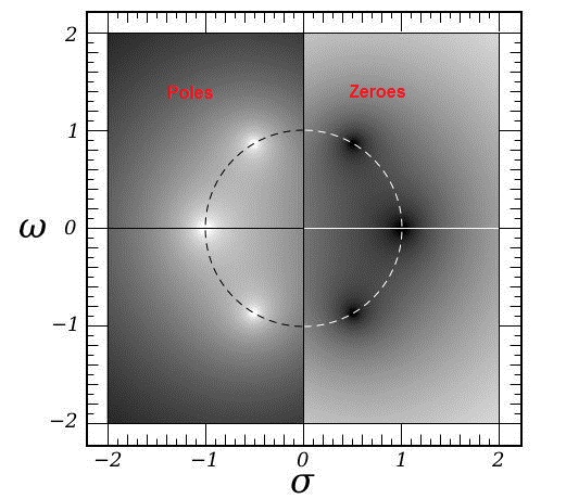
By the way, some loudspeaker imperfections can be described in terms of poles and zeros while others can't. Anything that's (at least approximately) linear time-invariant and lumped can be described in terms of finite numbers of poles and zeros, but anything that's distributed or nonlinear or time-variant can't.
For example, the impedance peak and low-frequency roll-off of a tweeter can be described in poles and zeros if you like (two of each, actually). The impact of different path delays is a distributed effect and can't be described with a finite number of poles and zeros.
When you measure the low-frequency impedance peak of a tweeter and fit it to a transfer function, you get the poles and zeros of the input current to input voltage transfer. When you take the reciprocal, so all poles become zeros and all zeros become poles, you have the admittance, the input voltage to input current transfer. Theoretically the poles of the admittance are also the poles of the voltage to sound pressure transfer, at low frequencies where distributed effects don't come into play, but the voltage to sound pressure transfer has its zeros elsewhere, namely in the origin.
Once you have the poles and zeros of the voltage to sound pressure transfer, you can try tweaking your filter such that it compensates for the tweeter roll-off. That is, take two zeros that would normally be in the origin and put them on top of the two tweeter poles.
I'm not claiming that this works better than other methods, but if you like to calculate transfer functions, you can have fun with this.
What I'm about to write now may seem obvious, but it took me a while to figure it out, so I'll write it anyway: when you want to synthesize a filter of order greater than two, it is usually easiest not to solve the pole locations. Instead you can calculate the desired coefficients of the numerator and denominator polynomials from the intended pole and zero locations and then equate the polynomial coefficients to what your circuit gives you. You can find an example in the part about third order filters in the attachment of https://www.diyaudio.com/forums/dig...8-dac-97-db-dynamic-range-12.html#post6753093
Last edited:
Nobody in their right mind would use Laplace Transform and Pole/Zeroes to design loudspeakers. Sorry! 😱
You get a simulator:
Software | Visaton
Two-ways are simple enough, here LR4:
One of my efforts:
Three ways are easy too, armed with a target response:
Troels' 3 way classic SEAS design:
Thing is, simulators don't use Laplace Transform. They use Hilbert Transform:
Hilbert transform - Wikipedia
And do all the tricky stuff for you. 😀
And do all the tricky stuff for you.
Hi Steve
Are you sure about that ? There are cases when the developer's target isn't a simple application of passive LR4 or the like.
It can be that he is implementing an active crossover with very low group-delay distortion (or even none at all - like the example posted by Bansuri). I don't think that all these simulators will automatically derive the necessary LTF for you.
Regards
Charles
Last edited:
Standard filters like Linkwitz-Riley just need their biquad stages looked up in tables. Each biquad stage represents 1 or 2 poles as a frequency and a Q-factor, which is directly useful for the standard IIR filter-realizations (analog or digital).Has anyone used Pole-Zero placement and Laplace Transform to design the crossover network of loudspeakers? Can you help to briefly explain the procedure? I have some basic knowledges of algebra and calculus. I’d like to try a new experience. Kindly help.
Or are you thinking in terms of matching an arbitrary desired response curve to a best fit set of poles/zeros? Normally for digital that's done with the Remez exchange algorithm to design a FIR filter to an arbitrary set of points on the response curve.
There are many useful functions to help with filter design in packages like Matlab, or Python's scipy.signal module.
After successfully derived transfer function and plotted poles and zeros, should I draw frequency response on magnitude curve (the absolute value of the transfer function; |H(S)|) and phase curve (the angle of the transfer function; /_H(S)) or a set of Bode plots (magnitude in dB scale and phase in degree scale)?
Also, is it too difficult to achieve if I were to draw the graphs by hand, I’m not professional in Matlab though.
Also, is it too difficult to achieve if I were to draw the graphs by hand, I’m not professional in Matlab though.
Last edited:
- Home
- Loudspeakers
- Multi-Way
- Pole-Zero placement, Laplace Transform, and crossover design