Some practical considerations from the soldering-iron end of things:
Is there some way to build into these sophisticated analyses the constraint that all the components you can buy come only in standard values - caps, coils, and even resistors? Or after you get the analysis done, re-calculating based on available components?
And even then, you need to buy a handful of each component in order to test and select the ones that match your model since manufacturing tolerances may be large?
At the least, this kind of analysis also demands some kind of sensitivity analysis in order to learn how badly the final result will be screwed-up by component variation.
B.
Last edited:
Component tolerances are as good as you want them to be. 10% error when converting to standard values is good enough IMO. Are you going to hear it?
Pole/Zero is terrific fun if you like function of a complex variable. And I have done it.
But really you will find little use for anything but various orders of Linkwitz-Riley and Butterworth solutions. Poles being on the unit circle to the left, and zeroes usually at 0 or infinity.
All been done for you already.
Jeff Bagby for 8 ohms:
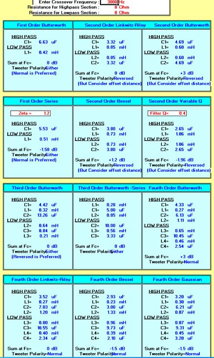
Nice calculators:
RF Tools | LC Filter Design Tool
2-Way Crossover Calculator / Designer
I tried Jeff's 8 ohm values for BW3:
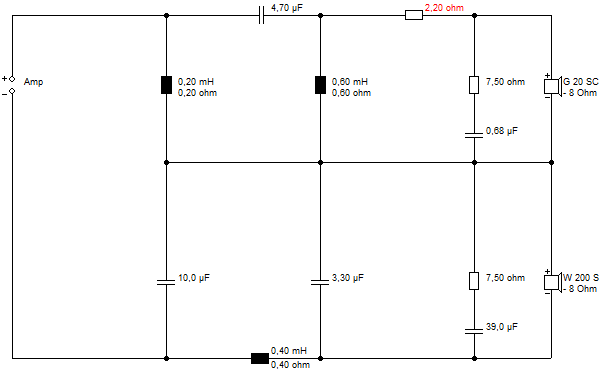
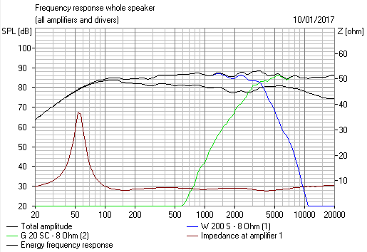
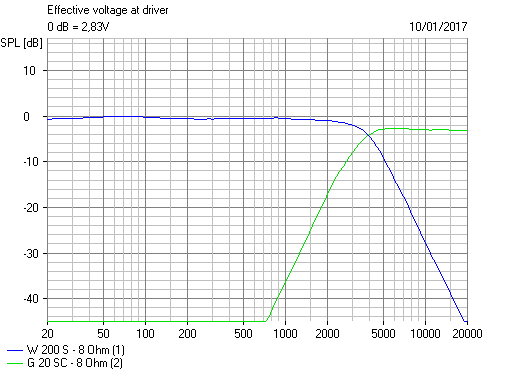
Not a bad BW3! Expected flat impedance from a constant power filter. No bafflestep correction, though the high-inductance bass has it built in largely. In practice, 6 ohms is usually nearer for 8 ohm nominal.
Pole/Zero is terrific fun if you like function of a complex variable. And I have done it.
But really you will find little use for anything but various orders of Linkwitz-Riley and Butterworth solutions. Poles being on the unit circle to the left, and zeroes usually at 0 or infinity.
All been done for you already.
Jeff Bagby for 8 ohms:
Nice calculators:
RF Tools | LC Filter Design Tool
2-Way Crossover Calculator / Designer
I tried Jeff's 8 ohm values for BW3:
Not a bad BW3! Expected flat impedance from a constant power filter. No bafflestep correction, though the high-inductance bass has it built in largely. In practice, 6 ohms is usually nearer for 8 ohm nominal.
Now, that is a rather casual "brush off" for my questions. With the careful discussion in this thread, maybe the practical question of tolerances and what their result might be seems worthy of a more precise answer.
B.
B.
Poles and zeros are just one of many ways to describe the dynamics of a linear time-invariant lumped filter. Frequency response plots and impulse responses are other ways to do it. No matter what representation you like most, you can always do sensitivity analyses, or decide not to.
It's handy that you can describe the dynamics of the filter with just a limited set of numbers, particularly when you want to come up with some non-standard filter circuit. For example, when you calculate the poles (or the characteristic polynomial) of your exotic filter circuit as a function of the component values and find that you can't possibly place them where you want without using negative or complex component values, you know your filter circuit isn't going to work. Happens to me all the time.
It's handy that you can describe the dynamics of the filter with just a limited set of numbers, particularly when you want to come up with some non-standard filter circuit. For example, when you calculate the poles (or the characteristic polynomial) of your exotic filter circuit as a function of the component values and find that you can't possibly place them where you want without using negative or complex component values, you know your filter circuit isn't going to work. Happens to me all the time.
Some practical considerations from the soldering-iron end of things:
Is there some way to build into these sophisticated analyses the constraint that all the components you can buy come only in standard values - caps, coils, and even resistors? Or after you get the analysis done, re-calculating based on available components?
And even then, you need to buy a handful of each component in order to test and select the ones that match your model since manufacturing tolerances may be large?
At the least, this kind of analysis also demands some kind of sensitivity analysis in order to learn how badly the final result will be screwed-up by component variation.
B.
One of the advantages of using pole-zero method is to be able to do some reverse engineerings of commercial loudspeakers.
The component values may be compromise as well as in other methods.
IMHO