I usually combine PCB with P2P: stuff like CCS, relatively complex PSUs, fixed bias, power management, etc., go on small PCB modules. I put ventilation holes under any resistor or heatsink that dissipates more than 0.5W.
Tube sockets and big caps go on chassis or on a sub-chassis, if I want to hide the nuts and bolts...
Tube sockets and big caps go on chassis or on a sub-chassis, if I want to hide the nuts and bolts...
you guys might be interested in this book: Symposium on Solder: Presented at the Fifty-ninth Annual Meeting American ... - American Society for Testing Materials - Google Books
specifically pages 115 and beyond and pages 113 and prior.
specifically pages 115 and beyond and pages 113 and prior.
A 1957 book has little revelance today (apart from some of the joining techniques), if you want to keep up with what is happening with PCBs and electronics assembly I would suggest joining or getting hold of IPC documantation, standards and research or having a look at PCD&F.
The materials and assembly techniques have improved greatly over the years, and today most electronic production is carried out using lead free solder.
If you are realy serious about the quality of your electrical/electronic assemblys the look at IPC-610 and 610 training, this is the most widely used standard in the world for quality of workmanship and joint quality.
Its a nice book from a historical point of view though.
http://pcdandf.com/cms/
http://www.pcb007.com/pages/pcb007.cgi
Last edited:
pfft sif, That book covers a whole lot more than just pcb's, but yeah if your not interested in bundles or old solder techniques...
Last edited:
Its pretty subjective and and a multitude of opinions everyone has between the two, but nothing wrong at all with experimenting with both and find out what suits you and if you like it or not.
You are right though PCB construction has been getting better as far better quality copper and thicker boards, yet in the past lots manufactures have really skimped on both of those.
They still do skimp on things, for commercial gear, quite often (all the time!) cost is paramount, look at the electronic kit we can buy these days for peanuts! There is also the high reliability, medical, aerospace, military and bespoke elctronics where quality is paramount. One of the equating factors though is SMD, compared to through hole, SMD assembly is cheep in manual labour costs, setting up a line is quite expensive but once set up you can produce thousand of boards 24/7.
Point to point is perfect for one offs and development for analogue and low speed basic digital. High speed digital prototypes require a PCB though as the development has to take in any effects PCB parasitics are goiung to have on the signal. So both have their place, but PCB's do have the advantage for EMC in todays RF rich envoironment, you can engineer EMC solutions into the layout (Henry Ott's tome is the best guide there is on this). And I believe that that is becoming more critical, especialy if you are worried about any influence on sound quality EMC may have.
Personaly I find point to point a PITA, just the hassle of doing it, so I will do myself a PCB, i also have the security of knowing the PCB connectivity matches the shematic exactly.
Freax, IPC-610 and other documents cover the same things, it is an interesting book, but with the advances in materials technology and construction techniques, I believe more modern material would be more relevant for todays assmbly methods, though having looked through it, and as I stated, some of the jointing techniques, forming a strong mechanical bond etc are still relevant.
Pfft, rather an onomatopoeic reply for 1st thing on a Saturday😛
Pfft, rather an onomatopoeic reply for 1st thing on a Saturday😛
Oh thats okay, its 9:39pm on Saturday here so its okay.
point to point terminal strip helps with the headache of working on ptp wiring, which is really just pcb!!!
I just thought of something...

point to point terminal strip helps with the headache of working on ptp wiring, which is really just pcb!!!
I just thought of something...
Last edited:
The precurser to SMD PCB's was the ceramic hybrid field that was very strong in the 70's. We would silkscreen .005" traced and spaces with gold ink, mount IC's , transistors as cut from the wafers and wire bond with gold wire. The resistors were thick film Ruthenium oxide laser cut to 1%, ceramic or tantalum capacitors could be soldered/ epoxied to the substrate. The most complex was a 6 metal layer, 19 IC die 256 wire bond hybrid that we did for HP. Approx 1"x3" in size. Raytheon was doing pacemakers with this technology.
The fastest circuit that we did slewed at 6,000V/u second.... We also did RF and IF circuits used in handheld radios, DTMF filters and other custom AF circuits... I did a power op-amp design but power density was a limitation of getting the heat out. I could only get 60watts out of it.
The fastest circuit that we did slewed at 6,000V/u second.... We also did RF and IF circuits used in handheld radios, DTMF filters and other custom AF circuits... I did a power op-amp design but power density was a limitation of getting the heat out. I could only get 60watts out of it.
They are still being done today, though instead of a ceramic inteposer standard PCB materials are used (though usually a higer Tg grade), BGA's etc.
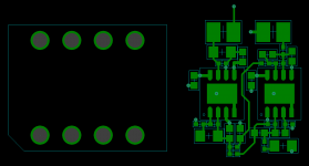
QPI-21LZ
One example with bottom terminations, others use gold plated semicircle s on the outer edges.
We did a coule of modules back in the days, the biggest problem was the difference in thermal expansion between FR4 and the ceramic, not so bad when they had through hole legs on a 0.1mm pitch, but became problematic as SMD apeared and sizes reduced.
They looked cool though especially if you had them hermeticaly sealed and gold flashed legs...
Just for the record, my favorite amps are my class A EL84 monoblocks in triode mode, so while I do favour PCBs I have a point to point amps, it will be these that one day I shall make machined copper interconnects and put in a clear polycarbonate case...one day.
Last edited:
- Status
- Not open for further replies.
- Home
- Amplifiers
- Tubes / Valves
- Point to point or pcb?