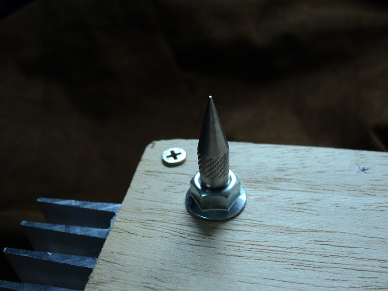
screwdriver meter
An externally hosted image should be here but it was not working when we last tested it.
zygibajt - Very nice so far!! I am looking forward to seeing how you make the rest of the connections.
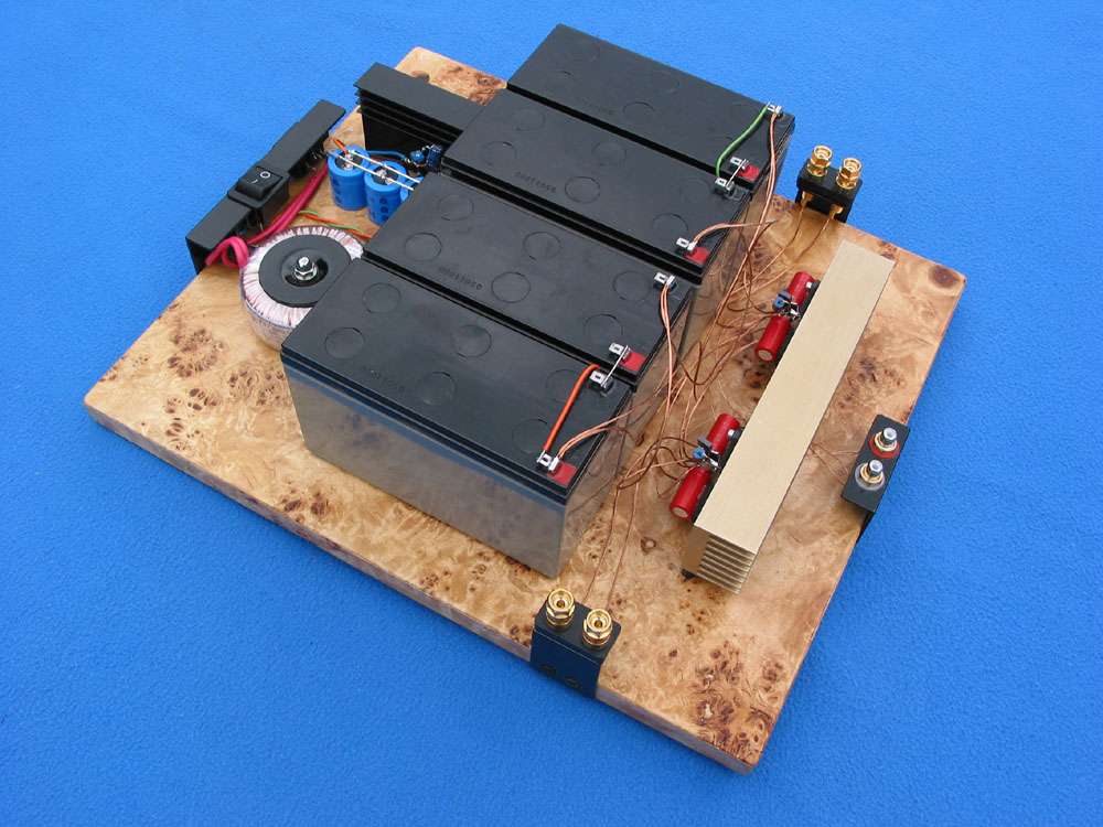
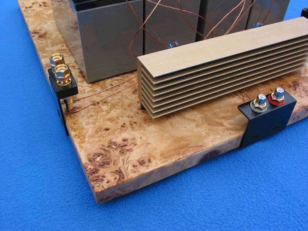
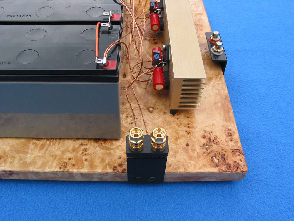
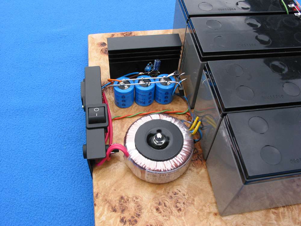
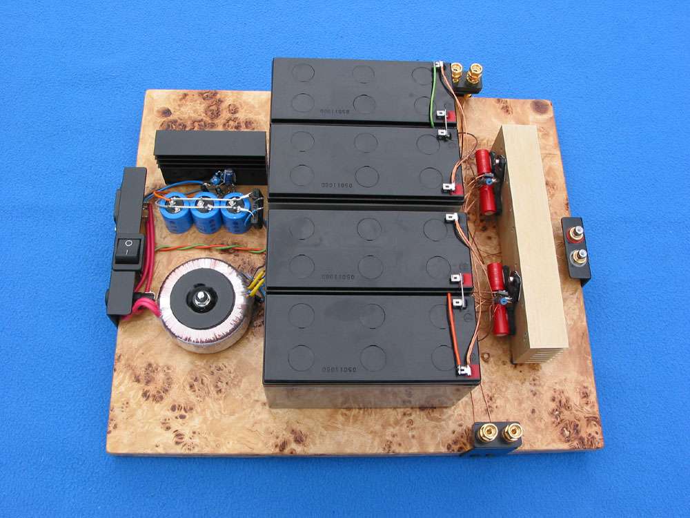
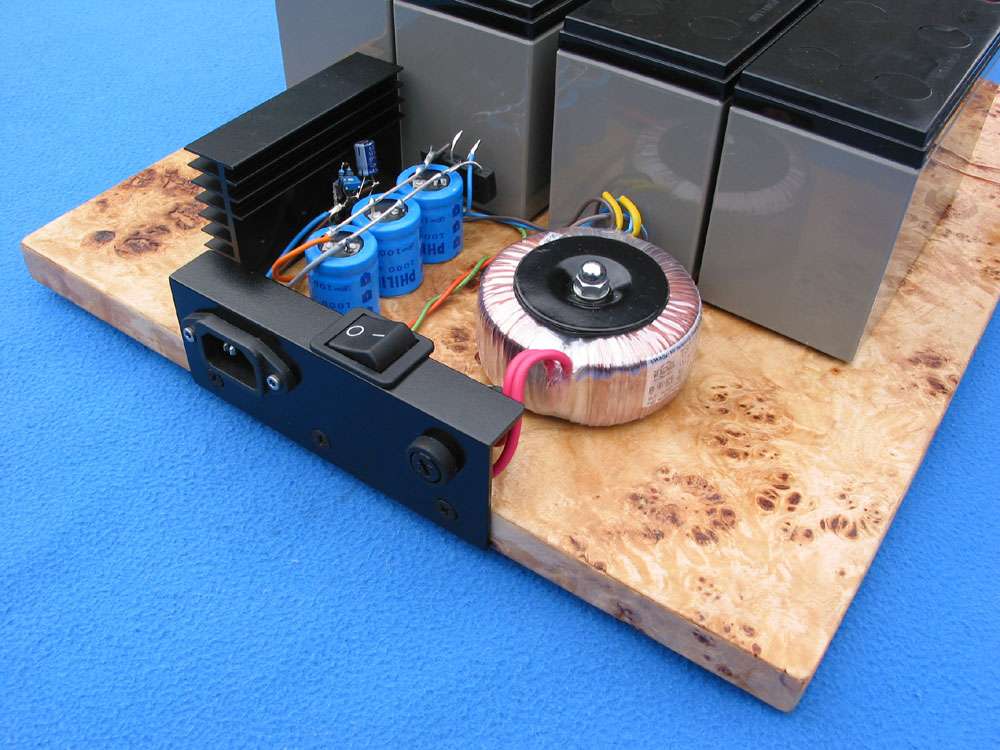
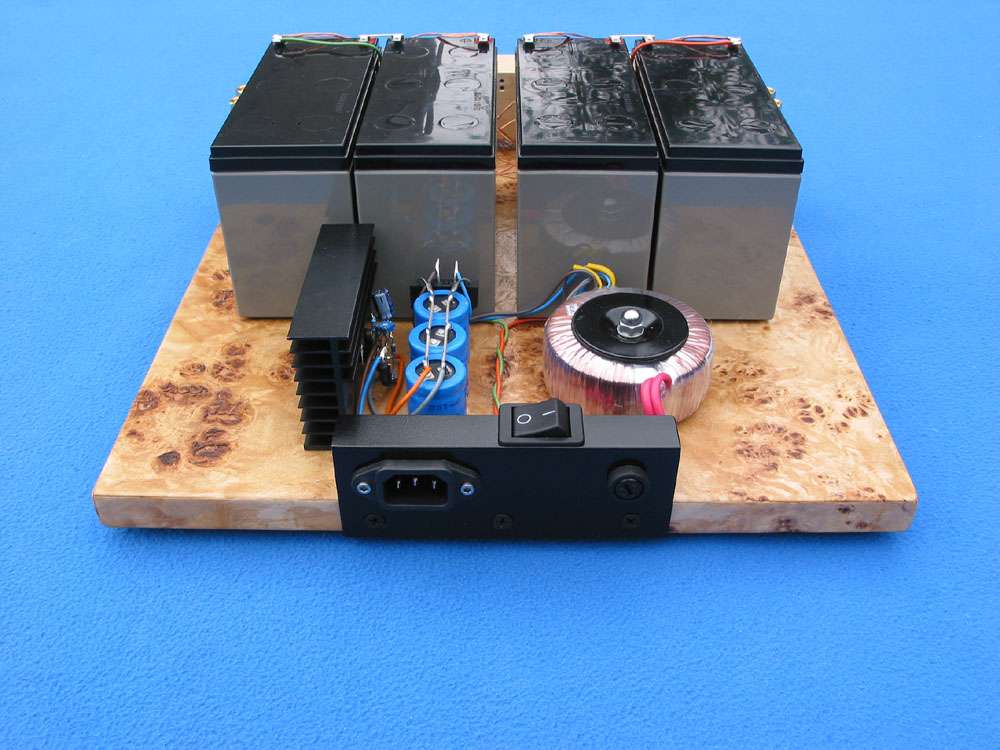
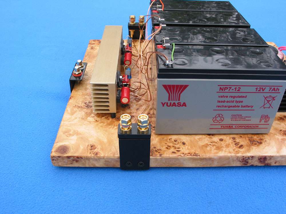
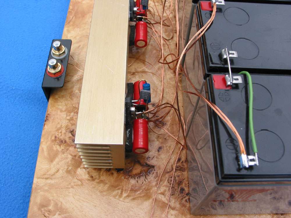
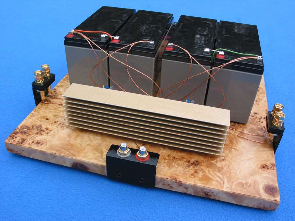
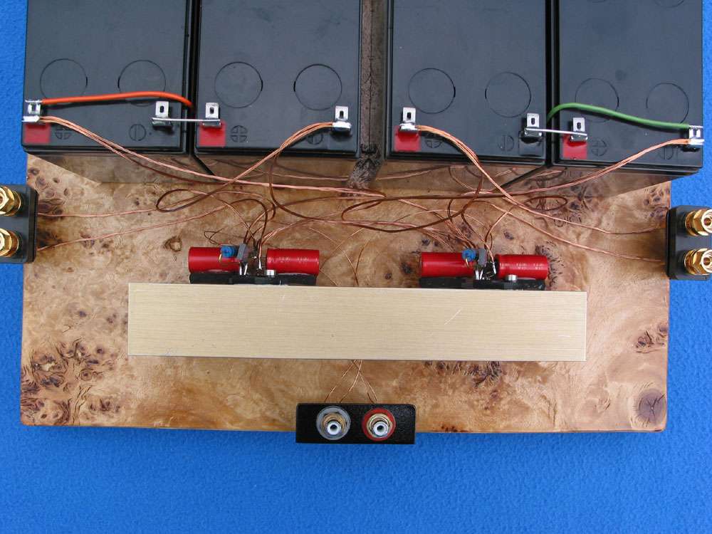
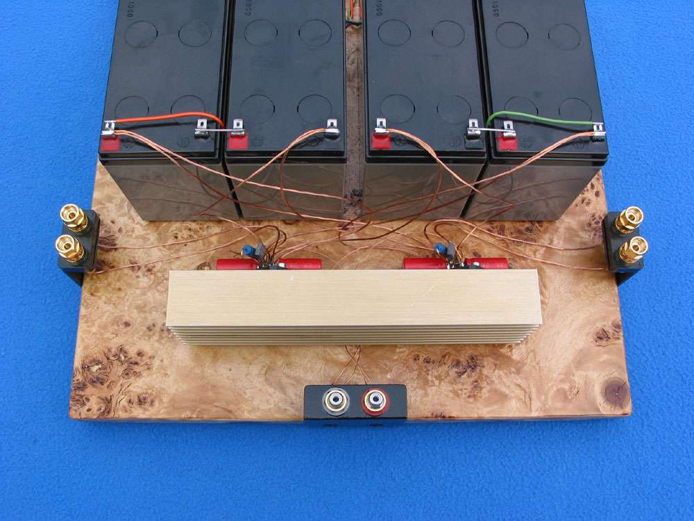
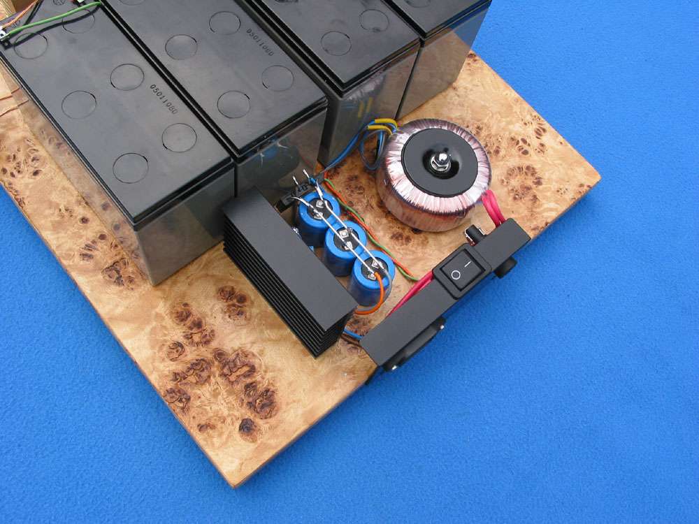
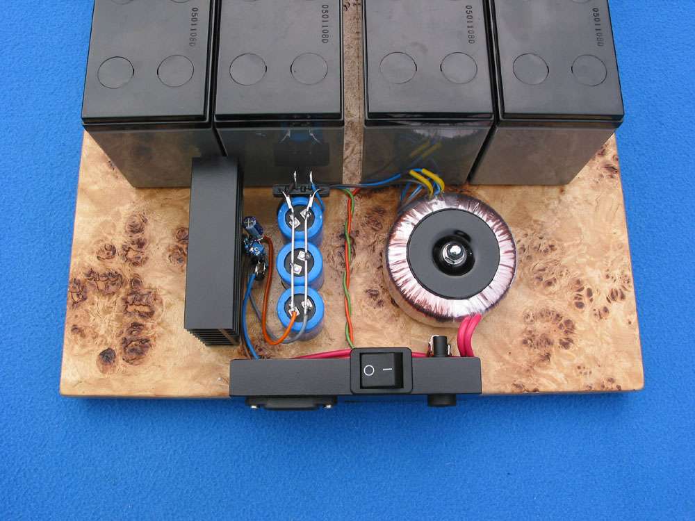
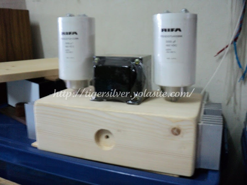
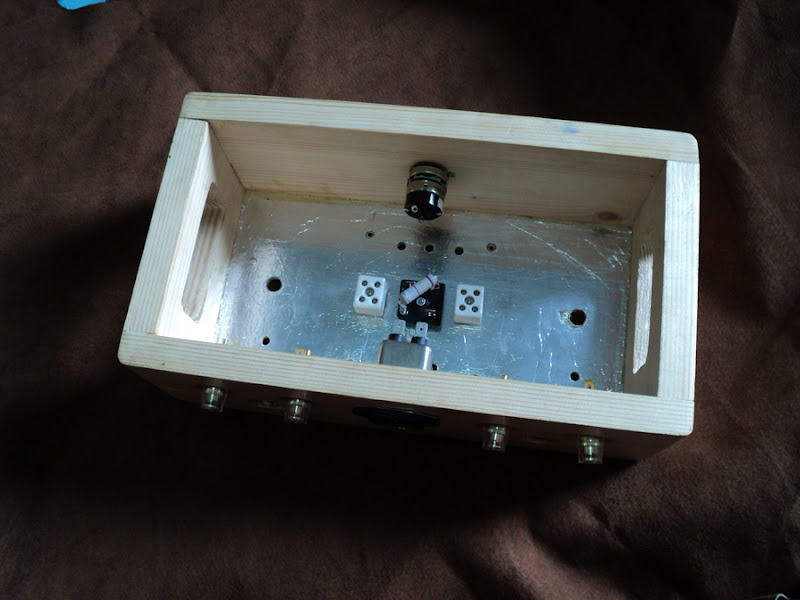
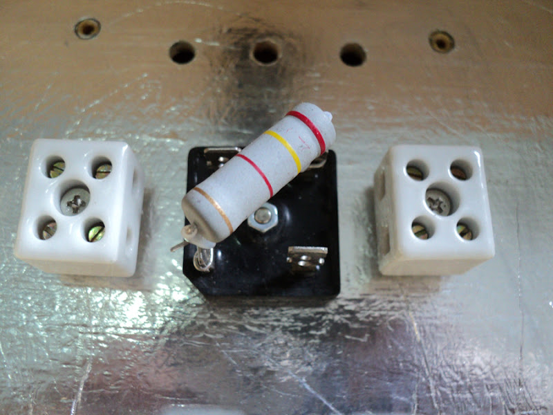
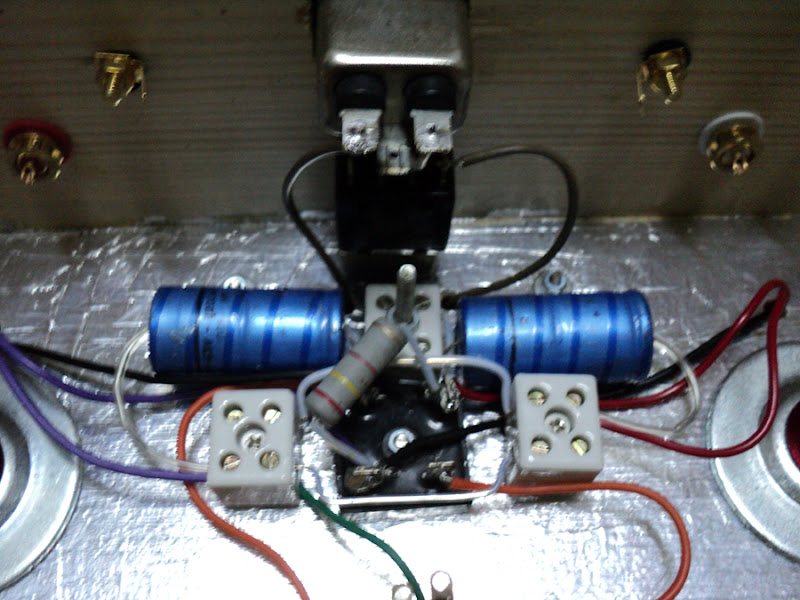
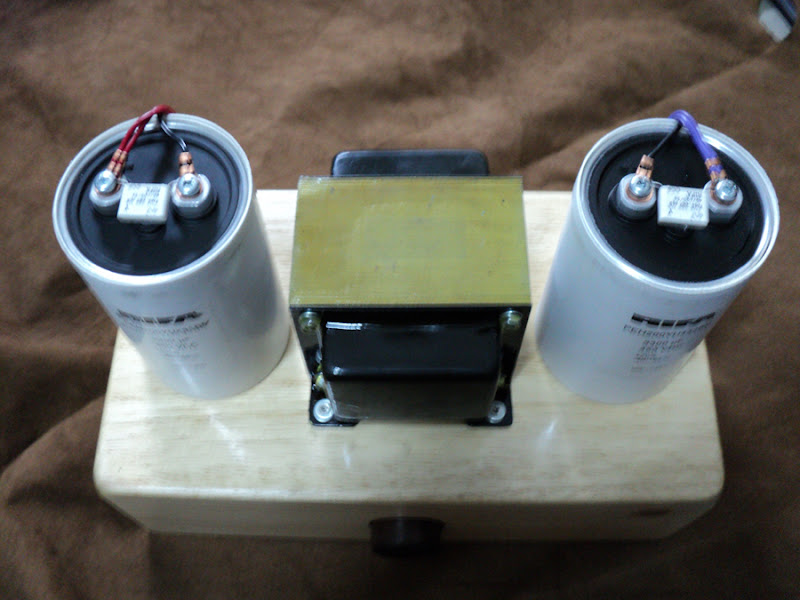
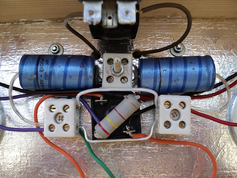
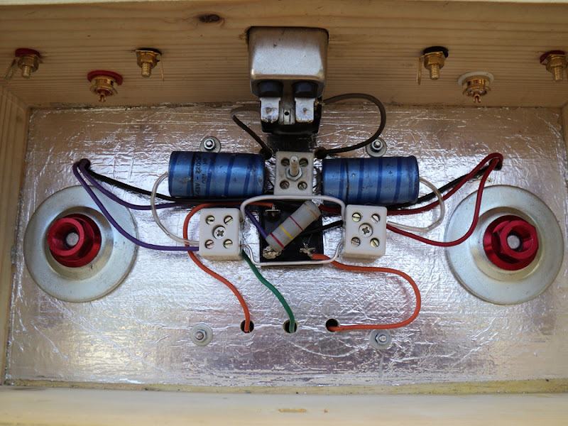
Well it is ot so far. The amp was built some 5 years ago when the whole GC chip amps boom exploded. It is supplied with Yuasa batteries and there is the charger behind them. The black power switch does not supply power (the circuit is soldered directly to batteries) but it switches the charger to batteries on anf off both negative and positive rail so when I'm listening only the batteries are connected to circuit. In the mean time I change all the wires to Cardas chassis wires, here with Vampire Cast copper ones. By today this GC is unused and the batteries are dead after extensive use for the past years. I'm more into class A amps by today. It is extremely important to keep the loop: negative cap/chip/positive cap as short as possible hence my pictures in this post. This makes the chip way stable and not reactive to capacitive loads.
An externally hosted image should be here but it was not working when we last tested it.
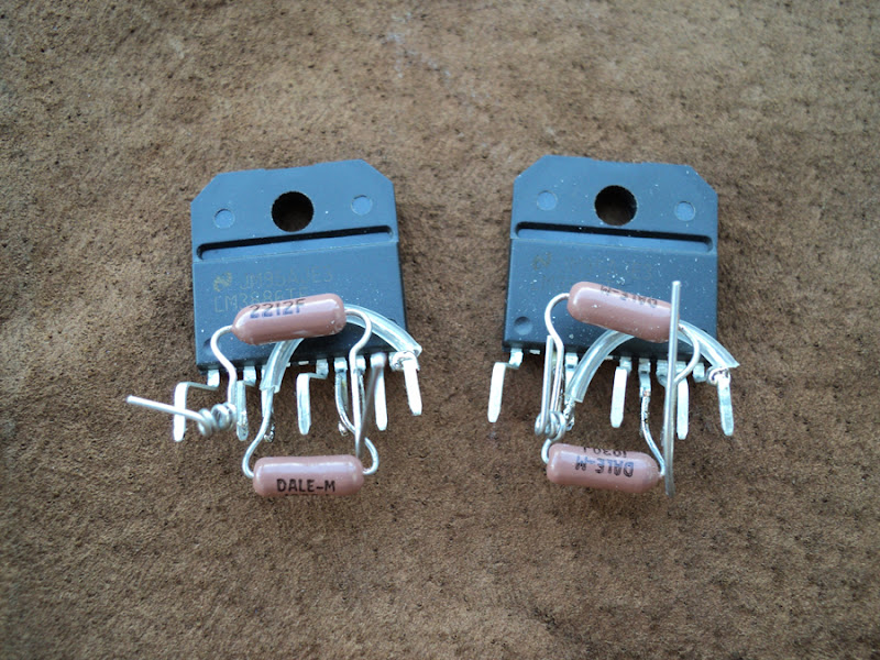
I was perusing the local electronics surplus store and saw that they had a handful of LM3886 in the bins, and thought it might be fun to wire up a pair and see how they do.
6L6,
JB Saunders? I'm heading there today...
😉
Yes, it was Saunders. 😀
No, I am not going there today, instead I'm hiking. 🙂
Do look thorough the tubes - they are selling an estate, and there is some wild stuff there lately!.
Do drop me a PM the next time you need to head that way, I would be happy to meet up there and then grab a cup of coffee and chat audio!
No, I am not going there today, instead I'm hiking. 🙂
Do look thorough the tubes - they are selling an estate, and there is some wild stuff there lately!.
Do drop me a PM the next time you need to head that way, I would be happy to meet up there and then grab a cup of coffee and chat audio!
Yes, it was Saunders. 😀
No, I am not going there today, instead I'm hiking. 🙂
Do look thorough the tubes - they are selling an estate, and there is some wild stuff there lately!.
Do drop me a PM the next time you need to head that way, I would be happy to meet up there and then grab a cup of coffee and chat audio!
I ended up making only a quick pass through for switches.
OT: I culled a batch of tubes right after they got the batch in, grabbed some 12BH7As and a bunch of rectifier tubes... Will touch base, Drop me a PM next time you go hiking 🙂
I've got a spare heat sink about 4"x 6"x 2" thick. I'm going to attempt to wire it point to point, mount the lm3886 to the heat sink and use it as a cover.
I'm just a bit concerned having stuff hanging from the top of the case might cause a few headaches down the road.
I'm just a bit concerned having stuff hanging from the top of the case might cause a few headaches down the road.
lm 3886

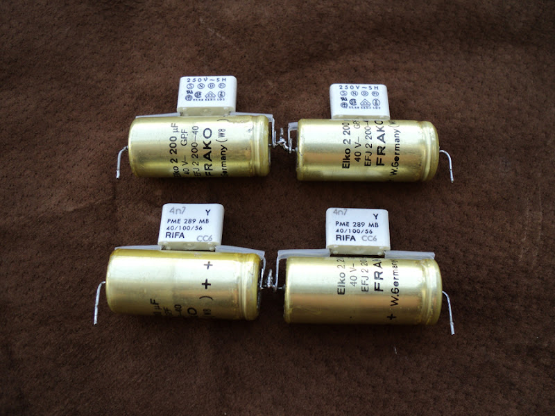


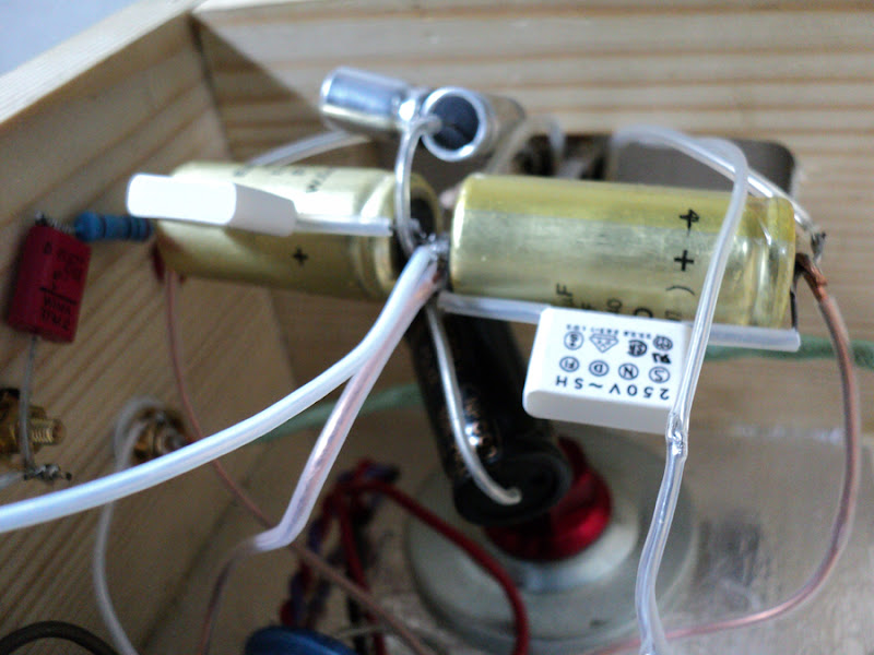
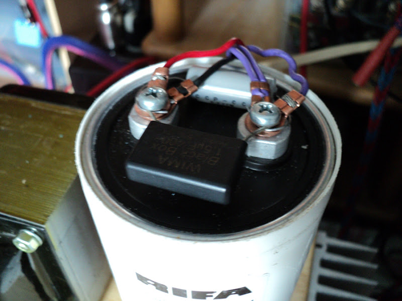
Too much bass as C rifa 👍 0.0047.
Improved use Rubycon photo-flash 200uf help.
voice is more clear.
Outside to some minor adjustments, including cylinders C.
Now ... the sound overall is desirable, may be change about C rifa 👍 4n7
---
If the wrong language. I'm sorry.
Too much bass as C rifa 👍 0.0047.
Improved use Rubycon photo-flash 200uf help.
voice is more clear.
Outside to some minor adjustments, including cylinders C.
Now ... the sound overall is desirable, may be change about C rifa 👍 4n7
---
If the wrong language. I'm sorry.
Bravo! Your builds are very well executed and have considerable style. How do you like this compared to your earlier build?
Hey, hey.
Will you guys PLEASE read Pano's blog about the posting vs. uploading of large images. It's extremely inconsiderate to post so many huge images in this way.
http://www.diyaudio.com/forums/blogs/pano/528-size-matters-posting-images-forum.html
w
Will you guys PLEASE read Pano's blog about the posting vs. uploading of large images. It's extremely inconsiderate to post so many huge images in this way.
http://www.diyaudio.com/forums/blogs/pano/528-size-matters-posting-images-forum.html
w
Hi all,
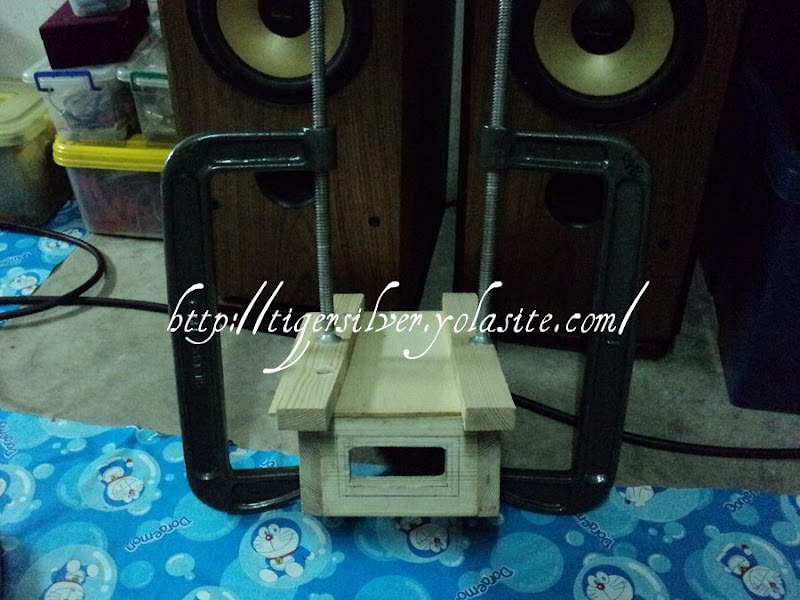
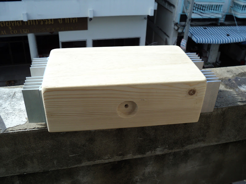
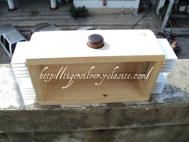
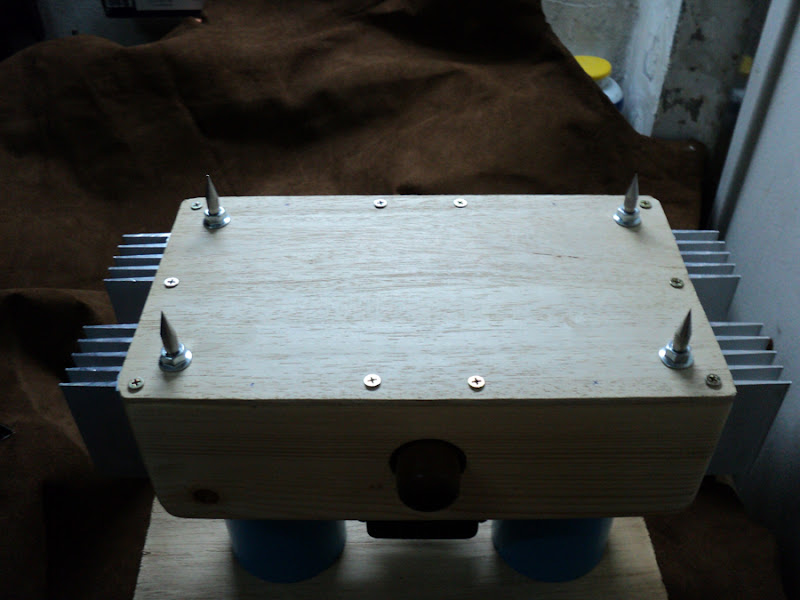
Well knock me down wiv a fevver! I thought I was the only one who made boxes from wood.
I did this in 2004 or 5 can't quite remember, anyway I used Thorsten's inverted circuit, this is my little web page about it: DIY Integrated Gainclone amplifier made in the UK from locally sourced components
Things have moved on a bit now and I'm thinking of rebuilding it to a non-inverted with a 2x 10,000 uf snubberized PS per amp. The transformers are 160VA 25V.
Great thread I love it really informative. Thanks.
Jim
Well knock me down wiv a fevver! I thought I was the only one who made boxes from wood.
An externally hosted image should be here but it was not working when we last tested it.
I did this in 2004 or 5 can't quite remember, anyway I used Thorsten's inverted circuit, this is my little web page about it: DIY Integrated Gainclone amplifier made in the UK from locally sourced components
Things have moved on a bit now and I'm thinking of rebuilding it to a non-inverted with a 2x 10,000 uf snubberized PS per amp. The transformers are 160VA 25V.
Great thread I love it really informative. Thanks.
Jim
Hi 6L6, I was just looking at the LM3886 datasheet (for an unrelated thing) and found this, which is related to Johnr66 and my original comments 🙂
Tony.
LAYOUT, GROUND LOOPS AND STABILITY
The LM3886 is designed to be stable when operated at a
closed-loop gain of 10 or greater, but as with any other
high-current amplifier, the LM3886 can be made to oscillate
under certain conditions. These usually involve printed circuit
board layout or output/input coupling.
When designing a layout, it is important to return the load
ground, the output compensation ground, and the low level
(feedback and input) grounds to the circuit board common
ground point through separate paths. Otherwise, large currents
flowing along a ground conductor will generate voltages
on the conductor which can effectively act as signals at
the input, resulting in high frequency oscillation or excessive
distortion. It is advisable to keep the output compensation
components and the 0.1 μF supply decoupling capacitors as
close as possible to the LM3886 to reduce the effects of PCB
trace resistance and inductance. For the same reason, the
ground return paths should be as short as possible.
In general, with fast, high-current circuitry, all sorts of problems
can arise from improper grounding which again can be
avoided by returning all grounds separately to a common
point. Without isolating the ground signals and returning the
grounds to a common point, ground loops may occur.
Tony.
Wintermute - great info... I will make some mods to my layout when I (finally) get around to building up this amp! 😀
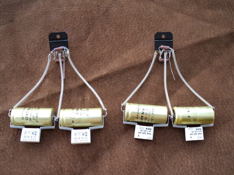
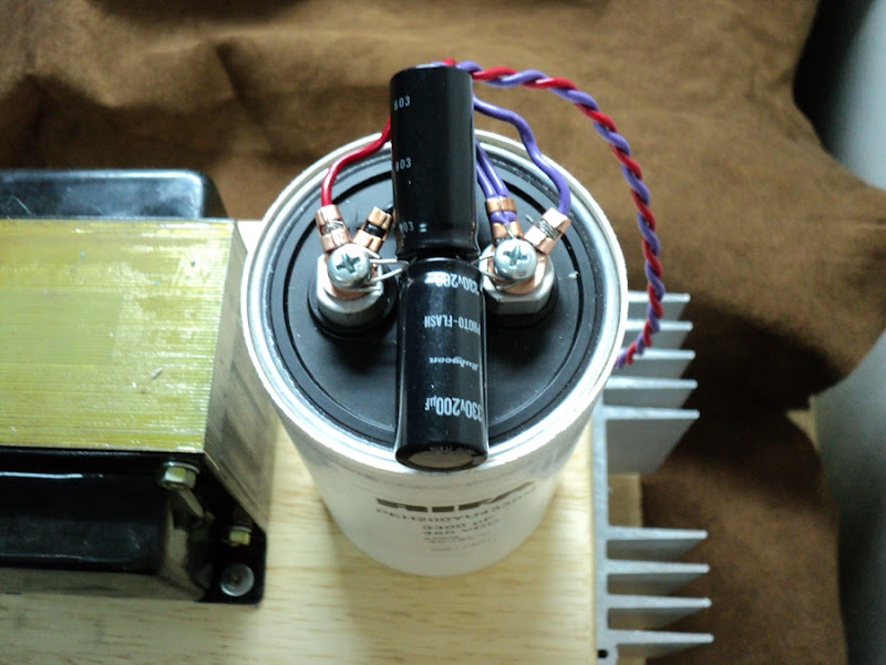
lm 3886 now Finish
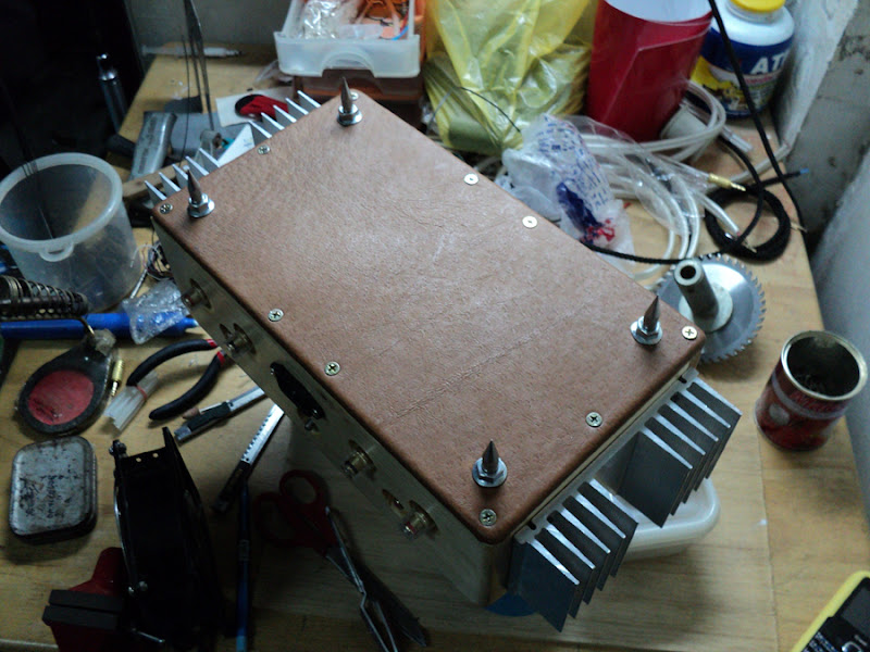
Small capa to maintain some balance of power.
And some act on the sound. biger capa can not act on the desired sound. i Use a small C to help.
Small capa to maintain some balance of power.
And some act on the sound. biger capa can not act on the desired sound. i Use a small C to help.
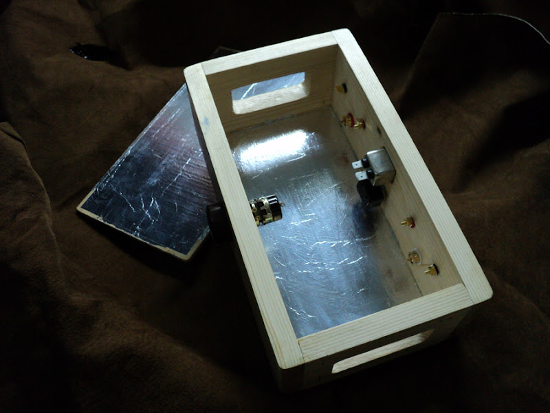
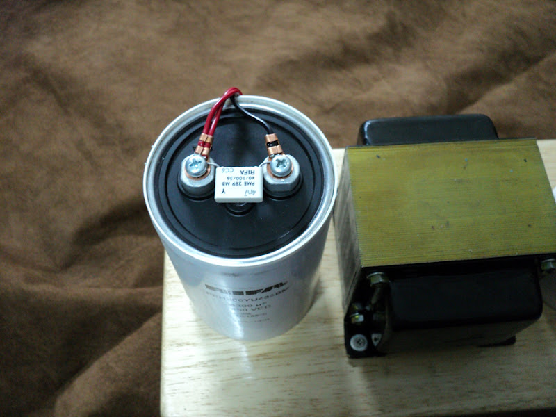
tigersilver: where do you get your pure copper ring terminal connectors above? i always see brass, or tinned copper, i would love some pure copper
tigersilver: where do you get your pure copper ring terminal connectors above? i always see brass, or tinned copper, i would love some pure copper
(pure copper ring terminal connectors )
If this..
I bought motorcycle accessories store.
Hi all,
I build this same amp and am wandering, some people do not use filtering caps at all and go directly from bridge to the lm3886. I did the same and although I does sound great, I want to know if someone did this and later added the PS filters and resistors to see if sound was better?
Does it become sluggish due to more circuitry?
Is it asolute neccesity in having the filter caps and resistors?
thank you
Last edited:
Impossible.Hi all,
I build this same amp and am wandering, some people do not use filtering caps at all
You DO NEED filter/storage caps in the supply under penalty of heavy unbearable 100/120Hz hum which makes amp UNUSABLE.
you CAN do that, why not?, but you MUST have main capacitors in parallel with LM3886 somewhere.and go directly from bridge to the lm3886.
Please show a picture of what you built, you MUST have filter caps in the supply rails.I did the same and although I does sound great, I want to know if someone did this and later added the PS filters and resistors to see if sound was better?
It does no matter where they are physically, all parallel connected points are at the same voltage by definition.
Sluggish? 😕Does it become sluggish due to more circuitry?
Not sure what resistors you mention, but filter caps are indispensable.Is it asolute neccesity in having the filter caps and resistors?
Hi,
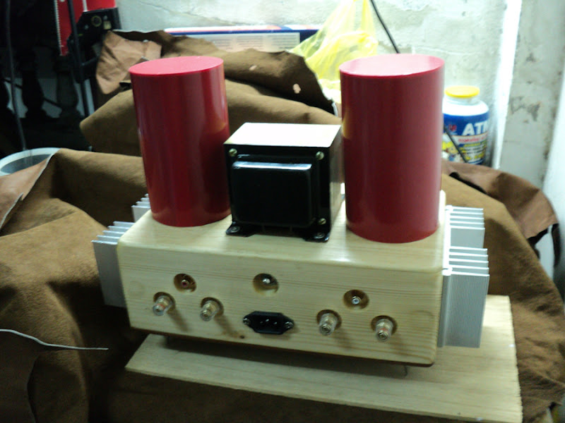
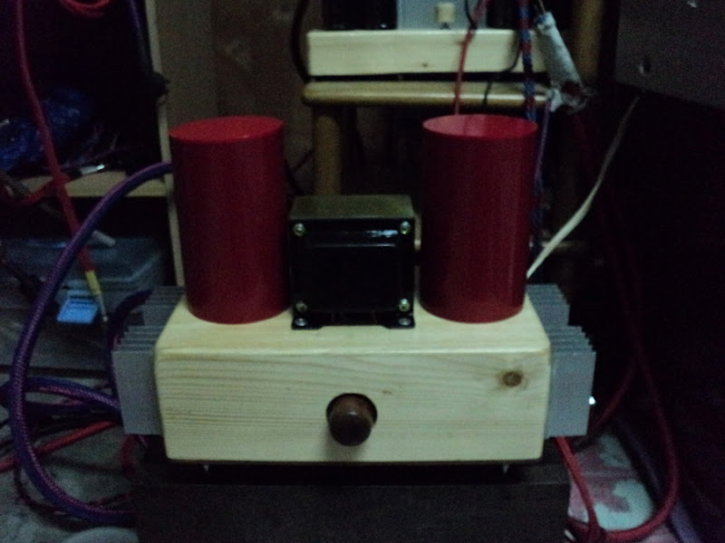
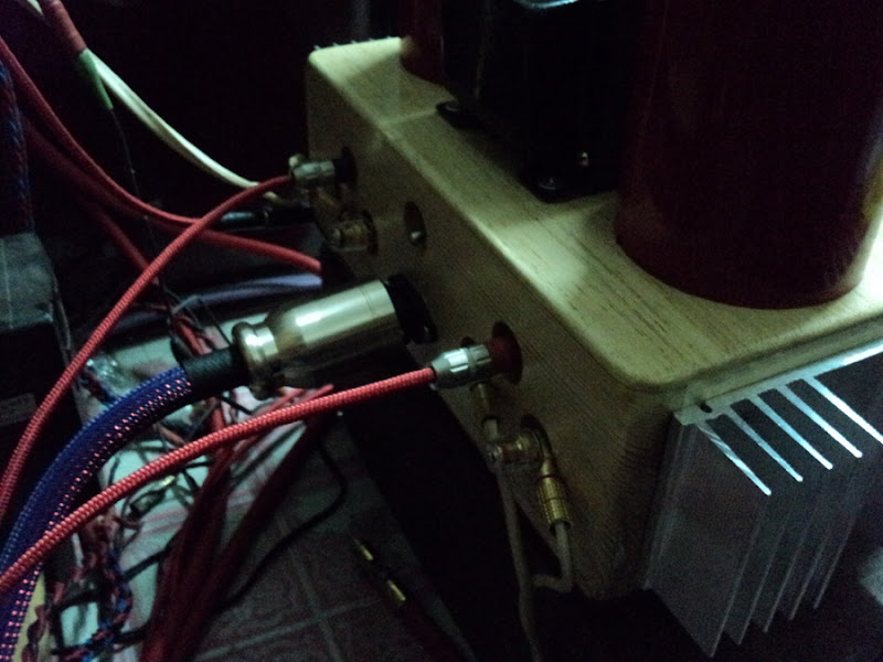
I built "Mick Feuerbacher Audio Projects " there are PS filter caps in parallel but only 2200mF.
Its pretty quiet, (still need to fix star Grounding).
Guess ill try to do bigger filter cap bank just to see how it sounds.
Thanks
I built "Mick Feuerbacher Audio Projects " there are PS filter caps in parallel but only 2200mF.
Its pretty quiet, (still need to fix star Grounding).
Guess ill try to do bigger filter cap bank just to see how it sounds.
Thanks
Last edited:
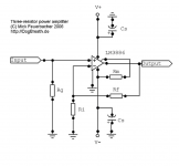
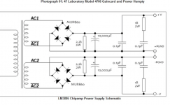
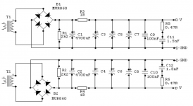
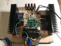
Attached is the schematic with two possible PS.
also project pic.
also project pic.
Attachments
- Home
- Amplifiers
- Chip Amps
- Point-to-Point LM3886