gain change = tone change
The arbitrary gain setting that you desire will probably conflict with the audio quality that you desire. So, I predict that you'd either give up the arbitrary gain setting or give up the audio quality. With a TDA729X chip, you don't get both simultaneously. Which one do you want?
Anyway, this topic needs double-checked carefully, not because of the gain, but because of the tone. And, there's the reason that all of my newer schematics for TDA729X have adjustable gain. It certainly won't give you the gain you want, but the dial can precisely give you the tone you want. The startup value on the adjustable schematic, results in gain of 38X. That dial works almost exactly like a bass/treble tilt control, and the fact that it happens to vary the gain is really unimportant.
P.S.
If this were a discrete amp, we'd just get on the simulator and fiddle the compensations in order to have the amplifier's sweet spot occur with the desired, arbitrary, gain setting. However, this is a chip and it is sealed shut.
The gain setting has almost nothing to do with the amount of gain you might need. The TDA729X chips will change tone with operating voltage and/or gain. Given the operating voltage, I think you might appreciate the tone of the amp best when set to 38X even though you don't need that much gain. At your operating voltage, even tiny gain changes makes dramatic changes to tone. Adjust carefully.Is more gain needed if it has line-mic pres,
and graphic eq(+-12vps) integrated at the chasis it´s going to be fitted?
As always, thank you very much for your time and attention.
The arbitrary gain setting that you desire will probably conflict with the audio quality that you desire. So, I predict that you'd either give up the arbitrary gain setting or give up the audio quality. With a TDA729X chip, you don't get both simultaneously. Which one do you want?
Anyway, this topic needs double-checked carefully, not because of the gain, but because of the tone. And, there's the reason that all of my newer schematics for TDA729X have adjustable gain. It certainly won't give you the gain you want, but the dial can precisely give you the tone you want. The startup value on the adjustable schematic, results in gain of 38X. That dial works almost exactly like a bass/treble tilt control, and the fact that it happens to vary the gain is really unimportant.
P.S.
If this were a discrete amp, we'd just get on the simulator and fiddle the compensations in order to have the amplifier's sweet spot occur with the desired, arbitrary, gain setting. However, this is a chip and it is sealed shut.
Last edited:
ok mr Daniel!
then it´s the100k fb res
and input pot?
these two are going bridged
with the 25-0-25 V 125VA TRAFO
for the 8 ohm speaker.
then it´s the100k fb res
and input pot?
these two are going bridged
with the 25-0-25 V 125VA TRAFO
for the 8 ohm speaker.
Unfortunately, bridged will double the output at the expense of cutting the audio quality in half; and also, bridged will double the load at the cost of decreased linearity, decreased longevity and decreased durability. There's an almost four times boost, but at cost to quality. Even so, it might work for a guitar amp or an auctioneer. I don't really know how to help you with a bridged amp.ok mr Daniel! then it´s the100k fb res and input pot? these two are going bridged with the 25-0-25 V 125VA TRAFO for the 8 ohm speaker.
Suggestion:
Try 1 chip first to see how you like that, and consider other options later.
Last edited:
Ok! since i still have them in the bench,
i´ll try your suggestions and adapt from there.
thanks for your advice
And what about the parallel for the 4ohm speakers?
It´ll have mixer and graphic eq infront of it...
i remember you mentioned i could use parallel chip
for the 8 ohm too and get better amp.
i´ll try your suggestions and adapt from there.
thanks for your advice
And what about the parallel for the 4ohm speakers?
It´ll have mixer and graphic eq infront of it...
i remember you mentioned i could use parallel chip
for the 8 ohm too and get better amp.
Last edited:
Yes! That's a push for power idea that really works! Chip amplifiers have built in limiters. But paralleling lets you output twice the power without running into the limiter.And what about the parallel for the 4ohm speakers?
You can try it either way and decide for yourself which method is more suitable for your application.
Ok, then the suggested fb string from your schem fits also 7293? right?
And its 27k-680+100vr-680uf+btb diodes(and small cap) si?
And it would be OK with 2xchips parallel.
I think i need to make a pcb..
And its 27k-680+100vr-680uf+btb diodes(and small cap) si?
And it would be OK with 2xchips parallel.
I think i need to make a pcb..
Yes, the only difference is the bootstrap cap is larger (68u~100u) with the parallel amp. Here's the PCB: TDA7293 Parallel 170W Mono Amplifier Board Kit 29 | eBayOk, then the suggested fb string from your schem fits also 7293? right?
And its 27k-680+100vr-680uf+btb diodes(and small cap) si?
And it would be OK with 2xchips parallel. I think i need to make a pcb..
Here's a thread about it, with photos: http://www.diyaudio.com/forums/chip...e-no-lossy-emitter-resistors.html#post3488798
That's nice and compact for good convenience with a point to point build. The lighter feedback current might make for slightly lighter bass; however, the amplifier is less trouble to fine tune and doesn't need trimmers in that case. I'd suggest to try your point to point TDA7294 solo build with the 100k vs 2k7,220uf and see if you like it.Or it could be OK with the 100k-2k7-220uf+smallcap?
Adjustable input load is useful, but not vital. It makes a minor midrange difference. The newer schematics show a trimmer constrained to 28k (applicable range 12k~27k) because those same schematics also have a 27k feedback resistor; and, whether matching those values up is good or not, really depends on the source.and an input trimmer?
thanks alot for your time and attention.
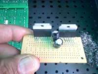
i´m trying now with a perfboard that i get locally
its got traces like to use dip ics, but i have your pictures,
and will try to follow your guidelines and the circuit you
made.I have to let aside the bridged amp and going to
start with the parallel 7293.
i´ll post images and comment how it sounds.
thanks again
martin martinnez
uruapan michoacan
intermediate
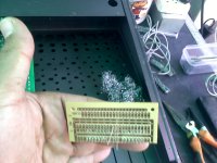
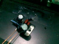
this is what ihave
😎
this is what ihave
😎
Attachments
Last edited:
more
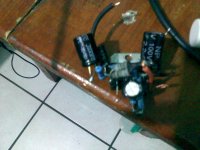
this one for testing. No place 4 the caps!
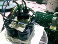
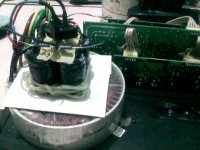
small Power Supply.
pointo pointed...
this one for testing. No place 4 the caps!
small Power Supply.
pointo pointed...
Attachments
Last edited:
the boards on post 131 are waiting confirmation, they´re crowded and yet more parts
tobe soldered. Anyway will finish if the chips turn tobe good not like the other pair.
Still have one p2p 7293 needto check again and test, also the parallel duo.
tobe soldered. Anyway will finish if the chips turn tobe good not like the other pair.
Still have one p2p 7293 needto check again and test, also the parallel duo.
Little table radios using that "fake" (re-mark) chip usually cost in the range from $50 to $380, depending on the skill of the marketeers. When it is re-marked to TDA7294, identification is practically impossible because the IC chip package is the same. An adequate defense seems to be to start up the amp with the Light Bulb Test and also a 12+12vac transformer. If it works at the low voltage, but not at the high voltage, then you've identified it.dead suspect of a fAKE!
For this reason, I prefer the TDA7293 chips, and see if the clip indicator pin works, which it tends to do on authentic chips.
Hi Daniel W! thanks.
then its better to try on low volts...
Please explain:
how would i know if #5 pin is working?
is it capable to drive a led?
I think the datasheet doesn´t show.
then its better to try on low volts...
Please explain:
how would i know if #5 pin is working?
is it capable to drive a led?
I think the datasheet doesn´t show.
The one that blew just made atiny snap, and a little
magic smoke got out.
Maybe +-35V was too much.
magic smoke got out.
Maybe +-35V was too much.
Well I don't know if TDA7294S/TDA7293 could drive an LED from pin5--I just drove an old analog voltmeter with it, temporarily to see if the expected circuits existed inside the chip.
- Home
- Amplifiers
- Chip Amps
- Point 2 Point (no PCB) for TDA7293, TDA7294, TDA7295, TDA7296.