Quite a few recent line-level projects here on diyAudio, are using Switch Mode Power Supply ("SMPS") wall warts to convert mains AC into the DC needed by audio circuitry. To name a few recent examples, the Starving Student II headphone amp, the First Watt H2 effects box, the B1 Korg NuTube preamp, and the Amp Camp Preamp+ (with headphone amp) are all powered by external SMPS warts. It's definitely a trend.
However, the 50-350 kilohertz switching circuitry inside SMPS modules, does make some members nervous. These folks are very concerned that high frequency noise on the DC supply, could compromise the sound quality of audio circuits. They desire a DC supply having very little high frequency noise, or, ideally, none.
I felt that, IF these pieces of audio gear could tolerate an additional 100 - 150 milliohms of resistance in series with their DC power supply, THEN we can build passive filter circuits to eliminate much of the SMPS high frequency noise. Admittedly I only studied their designs briefly, but I did come to the conclusion that all of SS-II, H2gen, B1Korg, and ACP+ can indeed tolerate an extra 0.15 ohms in series with the DC supply. So why not build a filter with a little extra series resistance, and see what happens.
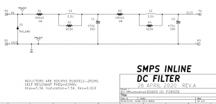
After some experimental tinkering, the circuit schematic in Figure 1 took shape. It has two stages of LC filtering, built 100% with through-hole components for easy soldering. Noise attenuation at 50 kHz is about 40dB (i.e. 100x); while at 200 kHz, noise attenuation is about 65dB (1700x). Input to output DC resistance is about 100 milliohms on the PCB. Then we need to add the resistance of external wiring (about 16 milliohms per foot for AWG-22).
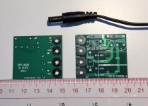
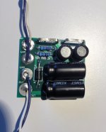
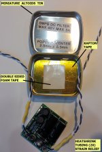
The filter circuit is laid out on a small PCB, 35mm by 40 mm (Figure 2). After stuffing, soldering, and attaching I/O connectors using blue and white "fly wires", the PCB looks like Figure 3. The first prototype unit was mounted inside a half size Altoids (breath mint) tin, using Kapton tape to electrically insulate the metal box from the rear face of the PCB. Then a piece of double sided foam tape keeps the PCB firmly attached in place. See Figure 4.
After the board is seated inside the enclosure and the I/O wires are pulled into their final position, two generous dollops of hot-glue are applied where the wires pass through holes in the enclosure. The glue keeps the wires fixed in place, and reduces the chances of abrading or scraping off the insulation.
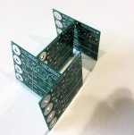
When ordering the PCBoards, I told the fab to build them extra-thin: 0.6mm. This didn't cost extra money, and it seems not to have slowed the order's speedy progress through the fab. Figure 5 is an ungainly attempt to show just how slender the boards truly are. After all, the thinner the PCB, the smaller an enclosure it can fit into. Since it costs nothing to build extra-thin boards, why on earth not?
With this PCB and these components, the design limits are 48 volts maximum and 3 amperes maximum. You shouldn't exceed 48V, no matter what the current. And you also shouldn't exceed 3A, no matter what the voltage.
Speaking of components, here is a Parts List. It's plain ordinary text holding comma separated values. You can copy and paste it into a file on your computer, and then MacGyver the data into any format you wish. Surprisingly, there is even a Wikipedia article about MacGyver.
PARTS LIST
A quick note on DC barrel connector plugs and jacks: the individual parts sold by Mouser and DigiKey, have unusually small solder-lugs to connect external wires. That's because these parts include a removable, screw-on housing which takes up valuable space. {Unlike high volume wall warts, whose plugs are simply molded plastic} So the Mouser/DigiKey plugs and jacks only accept smaller diameter (lower current!) wires. Tinker with them and decide whether you find them acceptable. If not, you can buy thick 2.1x5.5mm (and/or 2.5x5.5mm) extension cables, then cut each end to 15 cm length. Amazon also carries individual cables with quite hefty (AWG-18!) wires attached to plugs or jacks. Here is an example to start your search adventure (the first link) But honestly, there's a fantastic implementation in post #935 of this thread that is worth considering.
This filter circuit includes polarized (electrolytic) capacitors and a unidirectional diode. Thus it only works correctly when the input is positive with respect to ground. Most SMPS wall warts are arranged this way, with the center terminal of the barrel jack "Positive" and the outer ring of the barrel jack "Negative". However, a few pieces of audio gear {I'm looking at YOU, pioneer batch B1 Korg NuTube preamp!} have chosen to make the center terminal Negative and the outer ring Positive. For those weird situations, be VERY VERY careful to route the IN, OUT, and GND terminals of the SMPS filter PCB, to the correct pins of the barrel jack and barrel plug.
Ingenious builders, I am confident, will dream up amazingly clever ways to mount and package these PCBs -- in astonishing configurations that bear no resemblance to a pedestrian candy box. The nicest thing you can say about half-size Altoids tins is probably, "they are both cheap and easy to obtain." Innovative, talented people will do better, astoundingly better I'm sure. edit- and my prediction came true, see post #935 of this thread. Thus I request that you disregard half-size Altoid tins and please DO NOT CLICK the following link (the second link)
The unique identifier for this board is "PO89ZB" followed by "-A" indicating revision A. I've put that identifier into the thread title, for easier searching in future months or years.
Gerber files for the rev-A PCB are attached; anyone can send these files off to a PCB fab, and get as many boards built as they like, with my blessings and good wishes. Please consider giving away or selling any excess boards that you've accumulated, to other members of diyAudio.
HOWEVER, rev-A does not include mounting holes on the PCB. Member carsten.witt has modified the Gerbers to create a PCB which does include mounting holes. These Gerbers were used to build the boards & kits sold by the diyAudio Store. Please visit post #407 of this thread (here is a LINK) to download Gerbers WITH mounting holes.
_
However, the 50-350 kilohertz switching circuitry inside SMPS modules, does make some members nervous. These folks are very concerned that high frequency noise on the DC supply, could compromise the sound quality of audio circuits. They desire a DC supply having very little high frequency noise, or, ideally, none.
I felt that, IF these pieces of audio gear could tolerate an additional 100 - 150 milliohms of resistance in series with their DC power supply, THEN we can build passive filter circuits to eliminate much of the SMPS high frequency noise. Admittedly I only studied their designs briefly, but I did come to the conclusion that all of SS-II, H2gen, B1Korg, and ACP+ can indeed tolerate an extra 0.15 ohms in series with the DC supply. So why not build a filter with a little extra series resistance, and see what happens.
After some experimental tinkering, the circuit schematic in Figure 1 took shape. It has two stages of LC filtering, built 100% with through-hole components for easy soldering. Noise attenuation at 50 kHz is about 40dB (i.e. 100x); while at 200 kHz, noise attenuation is about 65dB (1700x). Input to output DC resistance is about 100 milliohms on the PCB. Then we need to add the resistance of external wiring (about 16 milliohms per foot for AWG-22).
The filter circuit is laid out on a small PCB, 35mm by 40 mm (Figure 2). After stuffing, soldering, and attaching I/O connectors using blue and white "fly wires", the PCB looks like Figure 3. The first prototype unit was mounted inside a half size Altoids (breath mint) tin, using Kapton tape to electrically insulate the metal box from the rear face of the PCB. Then a piece of double sided foam tape keeps the PCB firmly attached in place. See Figure 4.
After the board is seated inside the enclosure and the I/O wires are pulled into their final position, two generous dollops of hot-glue are applied where the wires pass through holes in the enclosure. The glue keeps the wires fixed in place, and reduces the chances of abrading or scraping off the insulation.
When ordering the PCBoards, I told the fab to build them extra-thin: 0.6mm. This didn't cost extra money, and it seems not to have slowed the order's speedy progress through the fab. Figure 5 is an ungainly attempt to show just how slender the boards truly are. After all, the thinner the PCB, the smaller an enclosure it can fit into. Since it costs nothing to build extra-thin boards, why on earth not?
With this PCB and these components, the design limits are 48 volts maximum and 3 amperes maximum. You shouldn't exceed 48V, no matter what the current. And you also shouldn't exceed 3A, no matter what the voltage.
Speaking of components, here is a Parts List. It's plain ordinary text holding comma separated values. You can copy and paste it into a file on your computer, and then MacGyver the data into any format you wish. Surprisingly, there is even a Wikipedia article about MacGyver.
PARTS LIST
Code:
2.1mm x 5.5mm male plug,xyz,490-PP3-002AH
2.5mm x 5.5mm male plug,xyz,490-PP3-002B
2.1mm x 5.5mm female jack,xyz,490-PR-002A
2.5mm x 5.5mm female jack,xyz,490-PR-002B
470 uF 50V capacitor,LS 5mm and Diam 10mm,80-ESH477M050AH4AA
2.2uH 7.5A 0.10R inductor,LS 5mm and Diam 9mm,652-RLB0912-2R2ML
68V unidir TVS 600W,DO-204 pkg,576-TP6KE68A
953ohm 1% 0.25W res,xyz,603-MFR-25FBF52-953R
0.04R 5% 1W current sense res,LS 12mm,66-OAR1R040JLF
A quick note on DC barrel connector plugs and jacks: the individual parts sold by Mouser and DigiKey, have unusually small solder-lugs to connect external wires. That's because these parts include a removable, screw-on housing which takes up valuable space. {Unlike high volume wall warts, whose plugs are simply molded plastic} So the Mouser/DigiKey plugs and jacks only accept smaller diameter (lower current!) wires. Tinker with them and decide whether you find them acceptable. If not, you can buy thick 2.1x5.5mm (and/or 2.5x5.5mm) extension cables, then cut each end to 15 cm length. Amazon also carries individual cables with quite hefty (AWG-18!) wires attached to plugs or jacks. Here is an example to start your search adventure (the first link) But honestly, there's a fantastic implementation in post #935 of this thread that is worth considering.
This filter circuit includes polarized (electrolytic) capacitors and a unidirectional diode. Thus it only works correctly when the input is positive with respect to ground. Most SMPS wall warts are arranged this way, with the center terminal of the barrel jack "Positive" and the outer ring of the barrel jack "Negative". However, a few pieces of audio gear {I'm looking at YOU, pioneer batch B1 Korg NuTube preamp!} have chosen to make the center terminal Negative and the outer ring Positive. For those weird situations, be VERY VERY careful to route the IN, OUT, and GND terminals of the SMPS filter PCB, to the correct pins of the barrel jack and barrel plug.
Ingenious builders, I am confident, will dream up amazingly clever ways to mount and package these PCBs -- in astonishing configurations that bear no resemblance to a pedestrian candy box. The nicest thing you can say about half-size Altoids tins is probably, "they are both cheap and easy to obtain." Innovative, talented people will do better, astoundingly better I'm sure. edit- and my prediction came true, see post #935 of this thread. Thus I request that you disregard half-size Altoid tins and please DO NOT CLICK the following link (the second link)
The unique identifier for this board is "PO89ZB" followed by "-A" indicating revision A. I've put that identifier into the thread title, for easier searching in future months or years.
Gerber files for the rev-A PCB are attached; anyone can send these files off to a PCB fab, and get as many boards built as they like, with my blessings and good wishes. Please consider giving away or selling any excess boards that you've accumulated, to other members of diyAudio.
HOWEVER, rev-A does not include mounting holes on the PCB. Member carsten.witt has modified the Gerbers to create a PCB which does include mounting holes. These Gerbers were used to build the boards & kits sold by the diyAudio Store. Please visit post #407 of this thread (here is a LINK) to download Gerbers WITH mounting holes.
_
Attachments
-
 SMPS_filter_schematic_revA.png26.3 KB · Views: 14,420
 -
 Ruler_PCB_plug.jpg262.2 KB · Views: 13,377
 -
 PCB_and_wires.jpg268.6 KB · Views: 11,339
 -
 Annotated_assembly.jpg378.7 KB · Views: 9,961
 -
 very_thin_board_edges.jpg268.6 KB · Views: 11,954
 -
PO89ZB_A_Gerber_Files_SMPS_Inline_Filter.zip14.2 KB · Views: 1,277
Last edited:

The lowest frequency I have seen in the larger switchers is 20 KHz, at about
10 mV amplitude.
10 mV amplitude.
Thanks, Nelson! This little half-Altoids-box filter is limited to 3A & 48V, which is about the most you can get out of a small wall wart, like the ones you'd use for preamps, line stages, and the like. To scale it up for higher power applications, you'd probably want to add a constant current startup limiter, plus some big ole bohunker filter capacitors after the L. The bigger Cs would reduce the LC filter's rolloff frequency, improving its attenuation at 20 kHz.
I always, ALWAYS get comparison price-quotes from
PCBShopper – A Price Comparison Site for Printed Circuit Boards
before deciding where I will send a brand new Gerber .zip file.
A list of past competition-winners may be found here
PCBShopper – A Price Comparison Site for Printed Circuit Boards
before deciding where I will send a brand new Gerber .zip file.
A list of past competition-winners may be found here
Thanks for sharing this, Mark!
I am about to build a (single) LC filter in front of a power amp SMS, a somewhat different need as for 5A.
I am still in the design phase and thought about 1.5uH / 5A for L and C will be 8700uF, so 2nd order filter with Fc= 1.4kHz. The SMPS frequency is 65kHz.
No clue if this additional filter between PS and amp will sound better or not, but I thought perhaps better trying that LC filter rather than a classical RC filter (had 0.34R and 8700uF in mind) that might somewhere "brake" too much reloading (Fc = 53Hz and 1st order only) not too mention voltage losses and voltage fluctuation varying with loads. Perhaps you had the same considerations when going LC rather than RC?
Trying to learn, I have few questions for you, if you don't mind:
1) What are the 953R resistors (R2 & R4) in parallel to the inductors for?
2) What are the 1W resistors for (R1 & R3)?
3) Last but not least, did you try your filter and notice any sonic improvement?
Many thanks for your help!
Claude
Last edited:
Claude, to design (or analyze) an RLC filter for SMPS noise reduction, you will need several tools.
The circuit presented in post #1 of this thread has more than one resonance, and the resonant frequencies are several decades apart. Therefore the circuit includes more than one component whose only job is to pacify & tame ("damp") a resonance. And part of your job as circuit analyst, is to calculate the damping factors it achieves, in order to decide whether they are sufficient to satisfy your own personal risk tolerance.
If this sounds like an intimidating & gigantic undertaking, don't get too discouraged. After all, it does take 4 years of university study to earn a degree in Electrical Engineering. This is complicated stuff that uses a LOT of mathematics. It certainly isn't simply memorizing a couple dozen formulas, which represent anything and everything you'll ever need to know.
_
- Confidence and intuition about the typical values of electrolytic capacitor ESR and ESL, perhaps starting with pages 5-7 of Cornell Dubilier's white paper
- An understanding of inductor self resonance, e.g., pdf link #1 , pdf link #2 , pdf link #3
- Manufacturer's detailed datasheets for the capacitor(s) and inductor(s) you plan to use in your design or analysis
- Skill and familiarity with Laplace transform mathematics; or if not this, then
- Extremely advanced skill and deep familiarity with LTSPICE simulation, especially in the frequency domain (".AC" type analysis)
If this sounds like an intimidating & gigantic undertaking, don't get too discouraged. After all, it does take 4 years of university study to earn a degree in Electrical Engineering. This is complicated stuff that uses a LOT of mathematics. It certainly isn't simply memorizing a couple dozen formulas, which represent anything and everything you'll ever need to know.
_
Thank you very much for the detailled answer Mark, I will get into all this.
The positive is I have these 4 years (and some more) already behind me, the negative is it was decades ago and I moved on to other things "meanwhile". That probably means I am much closer to Laplace than LTSPICE, but also that I have a lot of ground to cover in order to (re)gain some significant knowledge 🙂
But isn't the purpose of a hobby just to spend time in an enjoyable way?
Thanks again for all these pointers and links, I will dig into them with pleasure
Claude
Mark, thank you very much for designing these and making them available.
I ordered 10 of these from jlcpcb.com and will have 6 left over after I am done.
The first 6 people to pm me their address will get one each for free when these arrive.
I ordered 10 of these from jlcpcb.com and will have 6 left over after I am done.
The first 6 people to pm me their address will get one each for free when these arrive.
Mark, what would you recommend for a startup current limiter so that the charging of larger caps don't put an SMPS into over-current protection?
I've never tried to build an SMPS startup current limiter myself; I have no practical experience and I'm unable to say "method X worked well for me".
Exactly seven days ago another diyAudio member asked me this very same question on PM. To save thinking, and typing something new, here is copy and paste
Exactly seven days ago another diyAudio member asked me this very same question on PM. To save thinking, and typing something new, here is copy and paste
Keep in mind that there are no depletion mode Pchannel MOSFETs anywhere; they do not exist. There are dramatically fewer PNP power BJTs than NPN. There are dramatically fewer Pchannel power MOSFETs than Nchannel.
So I recommend that you design the circuits for whichever supply rail it is, that needs PNPs or Pchannel MOSFETs. Do that rail first. When it's all done and your design works great, it will be an easy and quick exercise to flop out another copy using NPNs and Nchannel MOSFETs for the other supply rail.
I think perhaps the first idea I would try, is a fairly simple one. Create a constant current source whose output current is 10% or 20% lower than the SMPS rated max current, and install it in series between the SMPS and the capacitor bank. At turn-on, let this CCS charge the capacitor bank at the constant current rate. The overcurrent protector won't trip because you're 10% or 20% below its trigger level.
Then after T seconds of this, activate a relay which shorts out the CCS, and connects the capacitor bank straight to the SMPS with a direct pathway. Choose T to be long enough to fully charge the cap bank, but not long enough to really annoy the human listener who has to wait an excruciating T seconds before music appears.
This is probably not the best way or the fastest way or the most elegant way or the lowest-parts-cost way. But I do think it's pretty easy to describe, and pretty easy to conceive an implementation ,that might have a decent chance of working correctly on the first try.
boards arrived today, they are tiny! I used jlcpcb and they are amazing value. Shipping cost 3.5x as much as the actual boards, thanks again for designing these.
Only two people have so far expressed interest in the spare 6 I have, PM me if you want one, I will be mailing them out over the weekend.
Only two people have so far expressed interest in the spare 6 I have, PM me if you want one, I will be mailing them out over the weekend.
Pity Konst's effort and amazing offer doesn't trigger more interest.
I can see myself using/testing Mark's latest toy on a low cost SMPS for a HP amp and if successfull possibly replicate then another one for my B1 Korg... we have and will have more SMPS in our beloved hifi devices, worth a go...
Thanks to make it happen and available
Claude
I can see myself using/testing Mark's latest toy on a low cost SMPS for a HP amp and if successfull possibly replicate then another one for my B1 Korg... we have and will have more SMPS in our beloved hifi devices, worth a go...
Thanks to make it happen and available
Claude
- Home
- Source & Line
- Analog Line Level
- PO89ZB, an inline DC filter for SMPS wall warts. Preamps, HPA, Korg NuTube, etc