In my experience, you will notice the differences if your hearing works at the switching frequency of the SMPS in question. I can noticeably hear the high-freq chipring, and once you hear it, it cannot be unheard. Of course, I've also confirmed this with measurements similar to those done earlier in the thread and I'd encourage folks to try this route to prove to themselves it works if their hearing can hear the artifacts.This forum is not super big into elucidating about subjective improvements, but you will find them if you look. That said, you will absolutely find a positive increase in sound quality, the filter is amazing.
😎
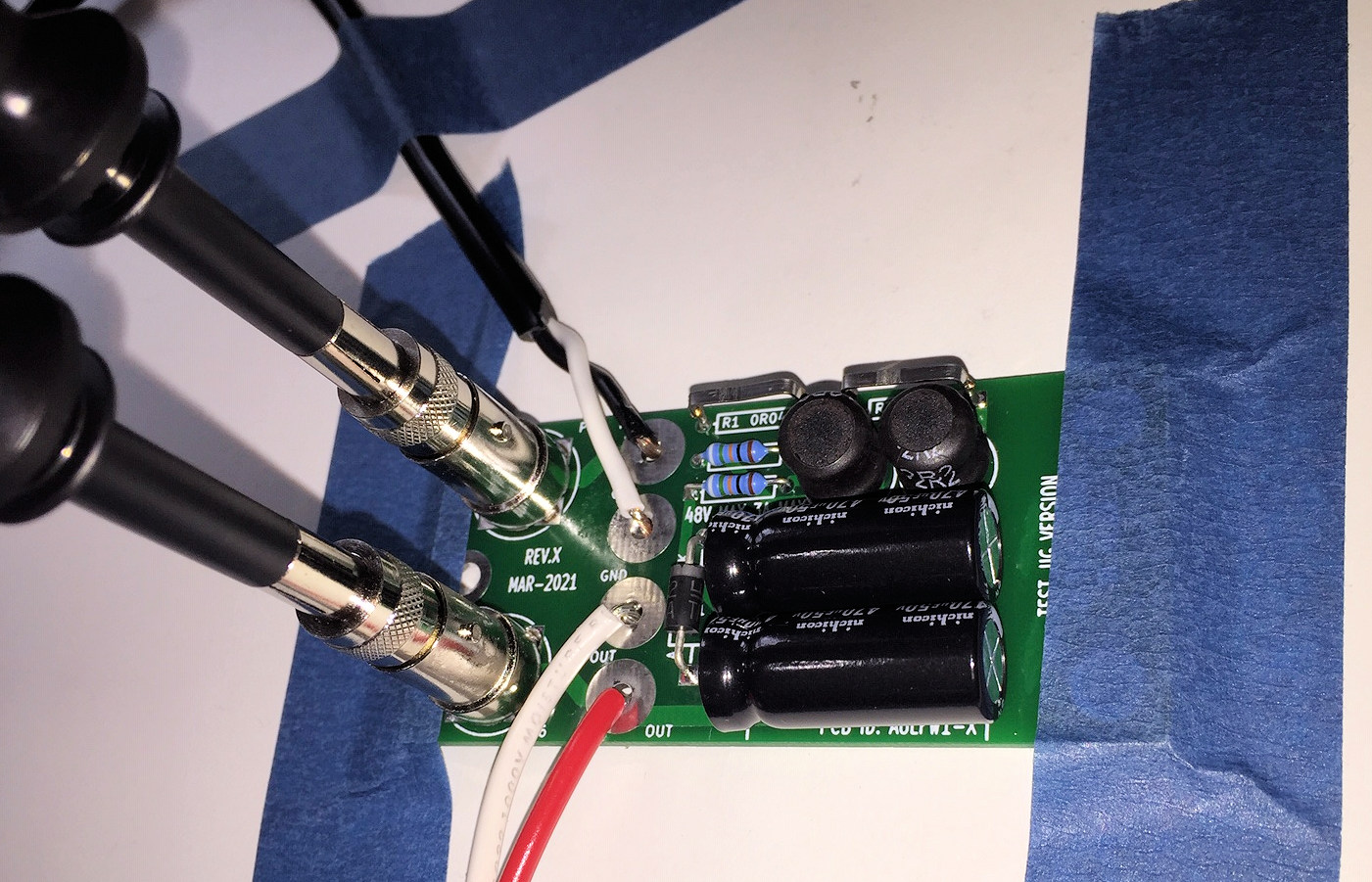
Measuring is fairly straight-forward at least for gross-level measurements to show you what its doing. If anyone is interested and the info on the thread is confusing, feel free to DM me as I'll be glad to help clarify. @Mark Johnson and @6L6 have been generous with their time educating me on how to do this a while back and I am happy to pass this on to anyone wanting to understand better.

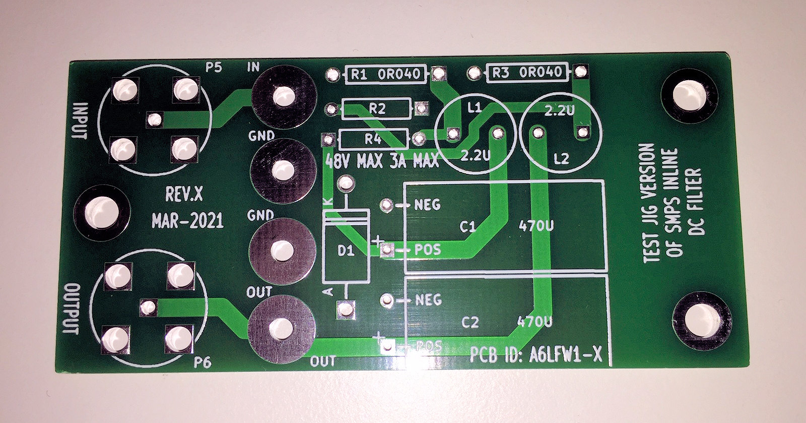
I have a couple extra PCBs for the testing version of the board, shown below. BNC jacks allow good signal integrity & low inductance grounding, as long as you've got BNC adapter tips for your scope probes. Sadly, the probe accessory kit which ships with many Rigol brand scope probes, does not. You may decide to purchase probes that DO include BNC adapters, or perhaps to purchase generic adapters and pray they'll fit your probes.
I'd be happy to give these to other diyAudio members, you just pay for the bubble mailer and the shipping cost: USD 5.00 . I won't ship internationally, sorry. I hate Customs forms.
I'd be happy to give these to other diyAudio members, you just pay for the bubble mailer and the shipping cost: USD 5.00 . I won't ship internationally, sorry. I hate Customs forms.
A few days ago, with one of Mark’s filters in hand, I haunted a few hardware stores looking for housing inspiration in the plumbing, electrical and household departments. This ritual may be familiar to a lot of diyers. When I returned empty-handed The Lady took the opportunity to remind me what strange beasts we diyers are!
I got my own back when, after rummaging through the garage, I came upon a solution that seemed specifically made for the filter. The photos below are of the filter fitted in the carcass of a Honeywell 5816 wireless alarm door/window transmitter. I had to change the transmitter some time ago and didn’t throw it out - another strange diyer trait, I’m told.

It fit so well I thought I’d share it here. The filter board actually snaps in to the manufacturer’s retaining tabs for the original PCB.
You then have the option of running the in/out cables through an existing opening or, like I did, carefully drilling the appropriate hole for your input jack of choice to make the filter and it’s new home ‘removable’ - and avoid cutting the cable of the SMPS. Only thing I did other than removing the Honeywell PCB (snaps out with a little gentle persuasion from a small screwdriver - or long female fingernails) was remove with a small wire cutter a moulding in the cover of the transmitter which is there to activate a tamper switch when the cover is closed/removed. You may be able to leave the moulding in.
A phone call to your friendly Honeywell alarm installation company will likely snag you a non-working 5816 for free or the following link gets you three brown ones for a little more coin.
https://www.alarmclub.com/5816br-ademco-brown-cover-for-5816-door-window-transmitter.html

I got my own back when, after rummaging through the garage, I came upon a solution that seemed specifically made for the filter. The photos below are of the filter fitted in the carcass of a Honeywell 5816 wireless alarm door/window transmitter. I had to change the transmitter some time ago and didn’t throw it out - another strange diyer trait, I’m told.
It fit so well I thought I’d share it here. The filter board actually snaps in to the manufacturer’s retaining tabs for the original PCB.
You then have the option of running the in/out cables through an existing opening or, like I did, carefully drilling the appropriate hole for your input jack of choice to make the filter and it’s new home ‘removable’ - and avoid cutting the cable of the SMPS. Only thing I did other than removing the Honeywell PCB (snaps out with a little gentle persuasion from a small screwdriver - or long female fingernails) was remove with a small wire cutter a moulding in the cover of the transmitter which is there to activate a tamper switch when the cover is closed/removed. You may be able to leave the moulding in.
A phone call to your friendly Honeywell alarm installation company will likely snag you a non-working 5816 for free or the following link gets you three brown ones for a little more coin.
https://www.alarmclub.com/5816br-ademco-brown-cover-for-5816-door-window-transmitter.html
I'm tempted to try one of these with a TPA3116 board. It won't ever be driven hard so I don't see an issue.
I've had a few of the dual rail boards in a box for a while and had finally got around to stuffing them. But getting the THT current sense resistors is (still) problematic. I'd considered just buying the DIYA at one point, but post Brexit delivery to the UK is OUCH!!!. So I was wondering about using SMD variants, particularly OARS1R040FLF that appears to fit the bill specification wise. It's also long enough that it should fit directly onto the solder pads for OAR1R040JLF and gets some spacing from the board.
To me this seems reasonable, but I confess to not knowing enough to be sure...
To me this seems reasonable, but I confess to not knowing enough to be sure...
I'll be at Burning Amp on Sunday, giving away a couple dozen bare PCBs. Here's what they look like, a stack of papers (schematic + parts list) with a PCB taped to each paper. I don't know exactly where I'll find an empty piece of exhibit table to place them, look around to find the stack. If you don't want a bare PCB because you don't want to locate and purchase electronic components yourself, the diyAudio Store sells a complete kit of PCB + all components, here . If taxes and shipping fees and customs and duties and VAT are very high in your hometown, I am very sorry.
_
_
Attachments

You can save A WHOLE LOT of money by purchasing the PCB and electronic components yourself.
Just now, as an experiment, I downloaded the Gerbers (post #407 in this thread) to my laptop. Then I asked my PCB fab house "JLCPCB" for a price quote to build PCBs from those Gerbers.
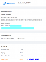
I told their quotation page that I wanted to order twenty (20) of the PCBs, and ship them to my building in Thorverton, Devon, UK. I selected DHL Express Priority shipping, which pre-pays customs and VAT and duties, and which enables direct shipping without stopping for government inspection or taxation stamps or anything else. You can see how much this service costs, in the attached image.
The total cost for twenty PCBs was GBP 46.16 including shipping. (They know I'm a Yank so they quote to me in USD.) £46.16 is quite a savings AND you can resell or give away the extra boards to DIY friends.
Oh by the way, have a bit of fun and look up that address in Google Maps. It's a real address and there's a real building there.
_
Just now, as an experiment, I downloaded the Gerbers (post #407 in this thread) to my laptop. Then I asked my PCB fab house "JLCPCB" for a price quote to build PCBs from those Gerbers.
I told their quotation page that I wanted to order twenty (20) of the PCBs, and ship them to my building in Thorverton, Devon, UK. I selected DHL Express Priority shipping, which pre-pays customs and VAT and duties, and which enables direct shipping without stopping for government inspection or taxation stamps or anything else. You can see how much this service costs, in the attached image.
The total cost for twenty PCBs was GBP 46.16 including shipping. (They know I'm a Yank so they quote to me in USD.) £46.16 is quite a savings AND you can resell or give away the extra boards to DIY friends.
Oh by the way, have a bit of fun and look up that address in Google Maps. It's a real address and there's a real building there.
_
Attachments
Have you bought 2500 0.04R 5% 1W current sense res,LS 12mm,66-OAR1R040JLF also?You can save A WHOLE LOT of money by purchasing the PCB and electronic components yourself.
Just now, as an experiment, I downloaded the Gerbers (post #407 in this thread) to my laptop. Then I asked my PCB fab house "JLCPCB" for a price quote to build PCBs from those Gerbers.
I told their quotation page that I wanted to order twenty (20) of the PCBs, and ship them to my building in Thorverton, Devon, UK. I selected DHL Express Priority shipping, which pre-pays customs and VAT and duties, and which enables direct shipping without stopping for government inspection or taxation stamps or anything else. You can see how much this service costs, in the attached image.
The total cost for twenty PCBs was GBP 46.16 including shipping. (They know I'm a Yank so they quote to me in USD.) £46.16 is quite a savings AND you can resell or give away the extra boards to DIY friends.
Oh by the way, have a bit of fun and look up that address in Google Maps. It's a real address and there's a real building there.
_
Only offer I found.
Anyway I ordered one from DIY shop to Sweden and 10 euro in tax and customs just to check it out so Im waiting now for delivery. 🙂
There’s 40 of the 3W 0.04R 1% in stock at RS….Have you bought 2500 0.04R 5% 1W current sense res,LS 12mm,66-OAR1R040JLF also?
Only offer I found.
Anyway I ordered one from DIY shop to Sweden and 10 euro in tax and customs just to check it out so Im waiting now for delivery. 🙂
£0.902 each
Post #1 of this thread contains a Parts List. The Parts List entry for the series resistors (0.04 ohms) tells you
Resistance in ohms, tolerance, wattage, and PCB hole-to-hole spacing for the resistor leads ("LS" means Lead Spacing On The PCB).
Any resistor with that resistance, that tolerance (or tighter), that wattage (or greater), which can fit on the PO89ZB PCB having that hole-to-hole spacing, is just fine.
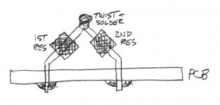
Yes, that even includes connecting two of Mouser P/N 588-WLAR020FET in series. They are in stock, they are tight tolerance (1% woo!), they have the correct resistance AND the correct wattage rating for two in series, and they are costly. But they are in stock. Hookup idea diagrammed below.
_
Resistance in ohms, tolerance, wattage, and PCB hole-to-hole spacing for the resistor leads ("LS" means Lead Spacing On The PCB).
Any resistor with that resistance, that tolerance (or tighter), that wattage (or greater), which can fit on the PO89ZB PCB having that hole-to-hole spacing, is just fine.
Yes, that even includes connecting two of Mouser P/N 588-WLAR020FET in series. They are in stock, they are tight tolerance (1% woo!), they have the correct resistance AND the correct wattage rating for two in series, and they are costly. But they are in stock. Hookup idea diagrammed below.
_
Attachments
Last edited:
If you say it's ok and no antennas that pick up something, good. 🙂Post #1 of this thread contains a Parts List. The Parts List entry for the series resistors (0.04 ohms) tells you
Resistance in ohms, tolerance, wattage, and PCB hole-to-hole spacing for the resistor leads ("LS" means Lead Spacing On The PCB).
Any resistor with that resistance, that tolerance (or tighter), that wattage (or greater), which can fit on the PO89ZB PCB having that hole-to-hole spacing, is just fine.
Yes, that even includes connecting two of Mouser P/N 588-WLAR020FET in series. They are in stock, they are tight tolerance (1% woo!), they have the correct resistance AND the correct wattage rating for two in series, and they are costly. But they are in stock. Hookup idea diagrammed below.
_
50 centimeters of AWG-24 solid core hookup wire gives you 0.04 ohms (check the tables). And it's in stock today (link). If you coil it around a pencil to get a physically smaller resistor, the negligibly small inductance (calculate it here) actually helps, rather than harms, filter performance. But it's negligibly small so it helps a negligibly small amount.
The old TV show "MacGyver" provides many inspirations for pragmatic builders. So does Clint Eastwood's movie Heartbreak Ridge: "Adapt ! Improvise ! Overcome ! "
The old TV show "MacGyver" provides many inspirations for pragmatic builders. So does Clint Eastwood's movie Heartbreak Ridge: "Adapt ! Improvise ! Overcome ! "
- Home
- Source & Line
- Analog Line Level
- PO89ZB, an inline DC filter for SMPS wall warts. Preamps, HPA, Korg NuTube, etc