Hi,
Where can I find a good class-A (solid state) with a clean output of 25-30 Watts.
Thanks in advance,
Goldy
Where can I find a good class-A (solid state) with a clean output of 25-30 Watts.
Thanks in advance,
Goldy
You want to build these?
Assuming you are talking about DIY, solidstate...
Zen v4
SOZ
miniAleph
Aleph 3 clone
Krell KSA clone
JLH
These are all really great amps, they have different strengths, weaknesses etc. You'll want to read peoples comments to find which could be the amp of choice for your needs.
There are probably others, if you perform a forum search for these you'll find many people who have built and are building them here.
HTH
Stuart
Hi goldy,
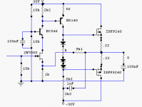
Here's one that's -
FET cascode input
comp MOSFET output with thermal comp.
DC coupled so no capacitor smearing
low cost low parts count
minimum Class A power consumption
can revert to class AB when you get your power bill!
A bit fiddly to set up
some DC drift.
Here's one that's -
FET cascode input
comp MOSFET output with thermal comp.
DC coupled so no capacitor smearing
low cost low parts count
minimum Class A power consumption
can revert to class AB when you get your power bill!
A bit fiddly to set up
some DC drift.
Attachments
If thi is your first amplifier constriction project than either the Aleph Mini, Aleph 3, or the he Krell KSA-50 clone are really pretty easy. They are very different sound amps though so investigate before you build. The nice thing about the Krell, the Mini, or the 3 is that they do not really require any super accurate transistor selection to get excellent results as long as you get all your devices from the same lot code.
Investigate, build, listen, enjoy!
Mark
Investigate, build, listen, enjoy!
Mark
To amplifierguru
Your fet amp schematic is very interesting. I’m planning to build this amp, even did pcb layout in the Eagle wich wasn’t hard at all. Can you give me (us) more info for successful results, like what else must be on the heatsinks except output transistors, and resistor values for safe class AB operation?
Also, wich diodes to use and right value of one resistor?
Thanks!
I agree Chicco_36,
This simple design of Ampguru's elegantly solves many of the usual issues in audio amp design.
I think it's very clever, and it's simplicity and originality shows considerable depth of thought about the problem.......
Congratulations, Ampguru!
Now, how does it sound, and what are its strengths and weaknesses in Class AB?
Cheers,
Hugh
are we looking at the same schematic?
amplifierguru's "elegant" single ended circuit has an output Cap! -talk about "capacitor smearing" - has to be an electo for 8 Ohms load (typos happen, I expect 100 mF was meant) - electros are much worse in measurable distortion than the polypro or even polystyrene you could use as an input coupling cap with a fet
without input offset or other adjust for bias the amp will be very "fiddly" to avoid offset from fet idss distribution eating into output swing - show pots or tell where Rs need triming

jcx said:are we looking at the same schematic?
amplifierguru's "elegant" single ended circuit has an output Cap! -
I think you will find that the 8R+100nF is a Zobel network and that the speaker is in fact direct coupled to the top end of the 8R resistor.
An output electrolytic should not be used on a dual supply rail amp due to the lack of a dc polarising voltage (unless of course the output is deliberately set to give a dc voltage, but then you would lose some output voltage swing).
there are a couple of schematic conventions to to avoid such confusion, simply extending gnd and output wires beyond the zobel would be a clue, attaching a R named Rload is definitive
nonpolar electrolytic output caps are preferred acording to Bateman, they have several times lower distortion than polar electros, even if the polars are biased
without output cap I would be suprised the cirucit would be safe without a regulated supply
nonpolar electrolytic output caps are preferred acording to Bateman, they have several times lower distortion than polar electros, even if the polars are biased
without output cap I would be suprised the cirucit would be safe without a regulated supply
"without output cap I would be suprised the cirucit would be safe without a regulated supply"
- Just like any other amp without DC servo, more or less...
Yes, 8R and 100nF is Zobel network on the output.
After all positive comments from Hugh Dean, I think it’s time to hear more from amplifierguru.
Here is first version of PCB I made, picture is mirrored, Zobel network just for info, I think best place for network is on the output conectors.
I’m not sure about 2N7000 pinout, I just put first small fet from Eagle library.
I wonder about maximum and minimum working voltage and what about IRF540 or IRF640 with complementary pairs, just for testing?
Regards
Attachments
Sorry guys I've been a little busy.
The drawing i posted was a little hasty so I'll elaborate.
Yes the 8R and 100nF is a zobel and not an output coupling cap.
Hi tschrama, appreciate the comments but you've missed some of the point of my original cct - given my 'preference' for Class AB I wanted a cct that could easily be biassed down to Class AB and still have credibility - so it needed to have good input stage PSRR. Hence the cascode. Also your alternate cct would be dissipating a rather high 3W rms in the feedback network.
jcx, I said it would be fiddly for setting DC offset. However this can be alleviated with a change to the ubiquituous 2N5457 fet and a 100K trimpot from the fet source (1K to ground) to the cascode base bias C. It would be beneficial to increase this C to, say, 10uF or more, for Class AB as this bias trimpot is an input.
The Bias R should be a 2K2 trimpot and will need to suit the threshold voltage of the MOSFETs used, otherwise no problem.
You will need to see what max output swing can be achieved using your own power supply then set the current through the 0.22R output resistors to suit. I = Vout peak /8. Around 2.7A for 30W. It will clip to the +ve supply first but will be slightly offset by the lower Nch losses and further if you wish to reduce the Nch output R - as long as you have thermal stability with your heatsink. ALL the diodes need to be in intimate contact with the heatsink.
Your heatsink will need to dissipate 160W continuously while not exceeding 75C (for burns) ! Around 0.33deg C/W!!!
Hi Chicco_36,
The results may be better if the IRFP240 in amplifierguru's schematic is paired with an IRFP9140 instead of an IRFP9240. Compared to the likes of Hitachi, Toshiba,Sanken and others, IRF's matching of "complementaries" leaves something to be desired.
hth, jonathan carr
hth, jonathan carr
 , drop me e-
 , pls
, plsWhat do U think about this ?
An externally hosted image should be here but it was not working when we last tested it.
Amplifierguru,
Can you update your schematic with new parts and right values according your post 12, specifically for class AB and voltages of say, +- 35V DC?
I moved diodes closer to heatsink and did better layout, but I will wait on your changes…
I think this amp will be very interesting project at the and!
Can you update your schematic with new parts and right values according your post 12, specifically for class AB and voltages of say, +- 35V DC?
I moved diodes closer to heatsink and did better layout, but I will wait on your changes…
I think this amp will be very interesting project at the and!
Hi chicco_36,
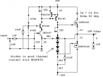
Here it is with a few refinements -
1. Not knowing the heatsink to be used I allowed 4 diodes in thermal contact 1N4004 should be OK.
2. I decided to provide the offset trim by making the stage one cascode load resistor a trimpot as there's no decoupling needed as in the divider suggested earlier so it will be less sus to supply commutation products in AB bias. Set to centre with no speaker connected and adjust for 0V.
3 I have increased bootstrap and divider C's for better LF performance and decoupling from supply.
Greg
Attachments
Chicco,
can you post your layout when you finished it ?
I'd like to add a Ball design, even if it's a minimalist.
And a nice one to check the difference between using an IRFP9240 and IRFP9140
can you post your layout when you finished it ?
I'd like to add a Ball design, even if it's a minimalist.
And a nice one to check the difference between using an IRFP9240 and IRFP9140
Good news, amplifierguru!
I will start working on the layout. Just one more question about 10uF capacitors. I assume they are electros, 10uF non-polar means huge affairs! No problem for me to put there Wima MKC4 63V, but pin to pin distance is 27mm. So?
I will exclude Zobel network from the PCB; I always put it on output connectors.
- Status
- Not open for further replies.
- Home
- Amplifiers
- Solid State
- Pls recommend a good class-A