You have a DC path to gnd in the - input line...data sheet has a cap in there.
http://www.st.com/web/en/resource/technical/document/datasheet/CD00000123.pdf
http://www.st.com/web/en/resource/technical/document/datasheet/CD00000123.pdf
thank you
but the connection I drove is good, it is take after an output cap, and please remember, this is transconductance amp so its connections are different than application note.
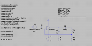
bellow corrected spice directives...
but the connection I drove is good, it is take after an output cap, and please remember, this is transconductance amp so its connections are different than application note.
bellow corrected spice directives...
Attachments
Last edited:
I think DUG is correct, you have a direct ground conection to the inverting input. It doesn't mater that the output is AC coupled, the input pin is still ground referenced.
(your .asc file wont run on a default LT installation. There are unknown models and subcircuits being called up that aren't included in your file)
(your .asc file wont run on a default LT installation. There are unknown models and subcircuits being called up that aren't included in your file)
Pawel please post a schematic of your work for people to see that dont use simulators
Thanks
Of course I will
but I still cannot run proper simulation, to check if this has a chance of working good🙄
please advise
how to create sub and cir files of TDA2003
with this model:
* IN+
* | IN-
* | | GND
* | | | OUT
* | | | | VPLUS
* | | | | |
.SUBCKT TDA2003 1 2 3 4 5
R_R6 1 N_1 150K
RCON_TAG2 1 0 1G
V_VOS2 N_2 2 0.65V
R_R8 5 N_3 20K
V_VOS1 N_1 3 1.3V
F_F1 2 3 VF_F1 0.5
VF_F1 N_3 3 1.8V
** Text Force **
.MODEL D D
D_D1 N_4 N_5 D
RCON_TAG3 N_6 0 1G
G_G1 N_7 N_6 VALUE { 5A*TANH(450*V(N_8, N_6)) }
R_R7 2 4 20K
F_F3 N_4 5 VF_F3 1
VF_F3 5 N_7 0
D_D2 5 N_4 D
R_RNOF1 5 4 1G
RFUD1 N_9 N_8 1
RFUD2 N_8 0 1G
RCON_TAG4 N_9 0 1G
R_RNOF2 4 3 1G
C_COUT 4 3 5pF
F_F2 5 3 VF_F2 1
VF_F2 N_5 5 0
X_U1 1 N_2 N_9 5 3 OpAmpConfigRails PARAMS: GDC=100K GBW=10 SLEW=1
+ ROUT=100 PM=45 VMP=0.65 VMN=0.65 W=10m
R_ROUT N_6 4 120m
.ENDS TDA2003
again
please nurse me
how to create
sub and asy
circuit of TDA2003
on the base of the model as in above post.
thank you in advance!
please nurse me
how to create
sub and asy
circuit of TDA2003
on the base of the model as in above post.
thank you in advance!
Hi
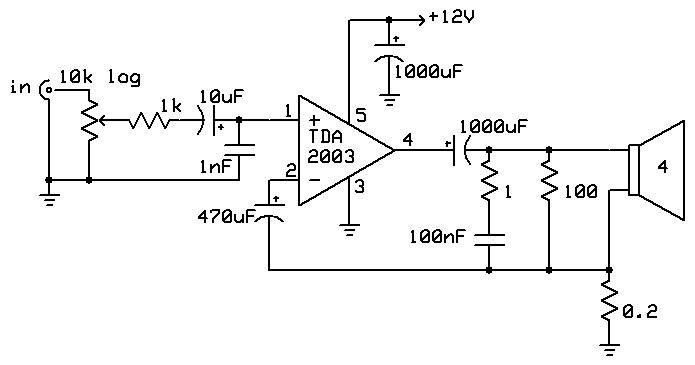
the circuit should look like this: http://www.diyaudio.com/forums/atta...nductance-current-amplifier-tda2003-trans.jpg
as reported in that thread the amp is working
hope this helps
the circuit should look like this: http://www.diyaudio.com/forums/atta...nductance-current-amplifier-tda2003-trans.jpg
as reported in that thread the amp is working
hope this helps
- Status
- Not open for further replies.
- Home
- Design & Build
- Software Tools
- pls help tp simulate transcond TDA2003 amp