I've finally figured out a system to collect data for plotting plate curves. Right now I am varying the voltage manually with a variac connected to a step-up transformer. The problem is figuring out how to run the voltage out past the dissipation limit without ruining the tubes.
Option 1 - Manually crank the voltage up fast, and disconnect the supply supply quickly when the voltage reaches the max.
Option 2 - Charge up a large-ish cap to the max voltage and then let it discharge through the circuit.
Samples are collected at a rate of about 100/sec, so it doesn't need much time at the high voltage. Option 1 is faster because it takes a long time for option 2 to work though the lower voltages. But option 2 seems safer.
Any comments, or better ideas, would be appreciated.
Thanks...
You might want to whip together a simple FET switch driven by a function generator to generate short HV pulses.
Jan
Jan
Or get a uTracer ( dos4ever.com)
the uTracer measures during 1 ms and prepares the next datapoint during several hundred ms
thus the tube never gets to hot even if one measures way above the maximum allowed Wa
the uTracer measures during 1 ms and prepares the next datapoint during several hundred ms
thus the tube never gets to hot even if one measures way above the maximum allowed Wa
How about using a programmable PSU? This thread has a bit of related discussion: http://www.diyaudio.com/forums/tubes-valves/287584-what-source-measure-unit-smu.html
How about just using some (selectable) plate resistors to limit the maximum dissipation (past the recommended Pda if you like) - as it was done in all the old curve tracers?
Last edited:
Just press a button to apply the anode voltage for a second or two while making the measurement, then release when done. The valve won't mind a second or two.
I went with the pushbutton method for now. Only change is that I needed to use a SPDT switch to connect the plate to ground when it's not energized, otherwise it floats to various random-seeming values.
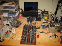
The first curve I got (Vg = 0.00) looks OK but needs some smoothing. I'm plotting in Excel so the math should be easy to get to, just haven't figured it out yet. Once nice thing about using Excel is that it can remove duplicate data entries, which at ~100 samples/sec means most of the data (all of it redundant).
Also a shot of a "steam punk" solderless breadboard idea I'm trying out. $40 worth of terminal strips off of E-bay, but worth the money if it makes wiring simpler. Haven't made up my mind yet.
Thanks to all for the help...
Attachments
- Status
- Not open for further replies.
- Home
- Amplifiers
- Tubes / Valves
- Plotting plate curves past dissipation limit