The easiest thing to do is create a Wiki titled "DIY Tools" or "DIY Worksheets"
and just start posting based on topics.
Vince
That Wiki set up is not straight forward to me having just looked at it. It is also pretty much empty at the moment it seems. I'll try another day 🙁
I use a PLLXO prototype for some time now and very happy with the results. To overcome the impedance issues i put everything between Nelson Pass B1 buffers:
High Pass
- Input --> B1 Buffer --> 1st order HP --> 2nd order HP (switchable) --> B1 Buffer --> volume control --> B1 Buffer --> out
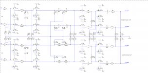
Same for low pass. I wass just designing a PCB for the final version for pcbexpress. It also incorperates a shelving filter for Baffle Step Compensation. The circuit is almost like below. But i have the Hp and LP the wrong way around.
By the way, the circuit below is for one channel balanced. This could also be a stereo single ended crossover, but then pot need shunt to ground.
High Pass
- Input --> B1 Buffer --> 1st order HP --> 2nd order HP (switchable) --> B1 Buffer --> volume control --> B1 Buffer --> out
Same for low pass. I wass just designing a PCB for the final version for pcbexpress. It also incorperates a shelving filter for Baffle Step Compensation. The circuit is almost like below. But i have the Hp and LP the wrong way around.
By the way, the circuit below is for one channel balanced. This could also be a stereo single ended crossover, but then pot need shunt to ground.
Attachments
Has anyone used that spreadsheet provided a couple posts back, and can they verify the caluclations are correct for a 2nd order high pass? Seems to me that it's not working correctly, but then I can't decipher the site it's originally derived from, either.
Can anyone clarify that formula and the way it's presented?
Peace,
Tom E
Can anyone clarify that formula and the way it's presented?
Peace,
Tom E
I'm checking & enhancing that little calculator,,, a cold is keeping my brain from working... i didn't get much done to-nite.
dave
dave
No, it's not. Did you try 2nd order high pass? I think that is what is screwed up.
I seek a 200hz high pass for an amp with 100k input impedance. Using 5k R1, the spreadsheet gives C1 160nF and C2 .00002nF and 50k R2. I'm not sure I understand the formula, but I think that's not correct.
Peace,
Tom E
I seek a 200hz high pass for an amp with 100k input impedance. Using 5k R1, the spreadsheet gives C1 160nF and C2 .00002nF and 50k R2. I'm not sure I understand the formula, but I think that's not correct.
Peace,
Tom E
2nd order high pass?
I seek a 200hz high pass for an amp with 100k input impedance. Using 5k R1, the spreadsheet gives C1 160nF and C2 .00002nF and 50k R2. I'm not sure I understand the formula, but I think that's not correct.
A 50k R2 with 100k input impedance will give a 33k R||. This needs a 0.024 nF cap.
You would be better to just set R2 to infinity (ie leave it out) and calculate C for 100k = 0.008 nF, then R1 could be bumped up to 10k, C=0.08 nF. This gives a better load for the pre-amp to drive.
dave
I'm checking & enhancing that little calculator
Not as slick or as well documented as it colud be, but i do believe it works.
http://p10hifi.net/planet10/TLS/downloads/PLLXO_Calculator.xls.zip
dave
Thanks for posting that. It seems to make a lot more sense now.
But now there is a new formula toward the bottom of the page at the web site for calculating C2, and it is totally baffling (ha ha). I don't think it is part of the Excel spread sheet formula. So which results do we believe?
Peace,
Tom E
But now there is a new formula toward the bottom of the page at the web site for calculating C2, and it is totally baffling (ha ha). I don't think it is part of the Excel spread sheet formula. So which results do we believe?
Peace,
Tom E
If it helps, the updated version came with the following advice from the author;
"Most of the changes are to the second order hi-pass. The straight formula gives a negative result when you have R2 > Ramp, so you would need a resistor in series rather than parallel to achieve desired R2, this will of course come with some attenuation, but you already have alot in the 2nd order lowpass."
"Most of the changes are to the second order hi-pass. The straight formula gives a negative result when you have R2 > Ramp, so you would need a resistor in series rather than parallel to achieve desired R2, this will of course come with some attenuation, but you already have alot in the 2nd order lowpass."
Can you circumfere amplifier input impedance?
Hi
Is it possible to put a small amplifier with gain 1 fixed input impedance and fixed output impedance between PLLXO filter and the power amplifier you use?
Thereby make the PLLXO indepentent of the power amplifiers input impedance?
best regards
uwe
Now that I read the whole thread I see thats what you can use those B1 buffers for.
Last edited:
Hi
Is it possible to put a small amplifier with gain 1 fixed input impedance and fixed output impedance between PLLXO filter and the power amplifier you use?
Thereby make the PLLXO indepentent of the power amplifiers input impedance?
best regards
uwe
Now that I read the whole thread I see thats what you can use those B1 buffers for.
Called a buffered PLLXO... in many cases, when needed, you can get away with buffer after the 2nd order HP
dave
Hi
Is it possible to put a small amplifier with gain 1 fixed input impedance and fixed output impedance between PLLXO filter and the power amplifier you use?
Thereby make the PLLXO indepentent of the power amplifiers input impedance?
best regards
uwe
Now that I read the whole thread I see thats what you can use those B1 buffers for.
That is what i did, i used discrete buffers (Pass Labs B1 buffers) in the following configuration
Input --> B1 Buffer --> BSC --> Hp 1st order PLLXO --> HP 2nd order PLLXO--> B1 Buffer --> HP volume control --> B1 Buffer --> output
same for LP. I received my PCB for my setup today. I will post some pictures of these soon.
I've often read that 2nd order xo's reverse phase and that 1 of the sets of drivers should have their polarity reversed. Is this also the case with a pllxo?
A crossover is a crossover. A PLLXO changes phase the same as an active line-level Xover or a speaker level Xover, so I would say yes.
Disclaimer: I am no expert.
P.S. I recently put transformers on my four-way first order PLLXOs. Huge improvement, most obviously in dynamics and bass weight!
OEP (OXFORD ELECTRICAL PRODUCTS)|A262A3E|TRANSFORMER, AUDIO, 1+1:6.45+6 | Farnell United Kingdom
Disclaimer: I am no expert.
P.S. I recently put transformers on my four-way first order PLLXOs. Huge improvement, most obviously in dynamics and bass weight!
OEP (OXFORD ELECTRICAL PRODUCTS)|A262A3E|TRANSFORMER, AUDIO, 1+1:6.45+6 | Farnell United Kingdom
- Status
- Not open for further replies.
- Home
- Loudspeakers
- Multi-Way
- PLLXO (v AXO v PXO) benefits/ Model?