A real cute version would be using 20 volt supplies, a J-fet (2 SK 170 V) as Q1 and IRF510 as Q2 and Q3. One ampere as steady current.
Perfect to use as a treble amp in a bi amp situation or to drive Lowthers, compression drivers and such.
Johannes.
Perfect to use as a treble amp in a bi amp situation or to drive Lowthers, compression drivers and such.
Johannes.
I dont think you need R71, R73 and C22.
That is the parts that create the bootstraping in order to make the resistors behave more like a CCS.
Since you have a true CCS you can safely do without them.
To me it seem like a sound circuit.🙂
I hope Mr Pass approves it to.
Cheers, Johannes.
That is the parts that create the bootstraping in order to make the resistors behave more like a CCS.
Since you have a true CCS you can safely do without them.
To me it seem like a sound circuit.🙂
I hope Mr Pass approves it to.
Cheers, Johannes.
J-fets and SQ ?
Since Q1 is so central and important to this circuit, it should be a J-fet, I think.
Since J-fets are not known to be high voltage, high power devices, paralleling and/or cascoding could be used.
Does this seem like a good idea ???
Since Q1 is so central and important to this circuit, it should be a J-fet, I think.
Since J-fets are not known to be high voltage, high power devices, paralleling and/or cascoding could be used.
Does this seem like a good idea ???
Cascoding carries a voltage loss penalty, otherwise it would
work fine. As long as a JFET is rated at the power supply
rail voltage, you should be fine.
work fine. As long as a JFET is rated at the power supply
rail voltage, you should be fine.
Thanks for the comments Johannes!
I thought about removal of the bootstrap and its resistors, but this left me with no option of altering the gain ratio of the power MOSFETs (as per Nelsons article). Also, some resistance is necessary above Q1 in order to bring the quintesent voltage at the output to something approching 21V (42V rail in my case). Do you have any other solution to how this can be done?
Seeing as how we live in the same city... How about you build a JFET version and we can compare results?!
Hälsningar,
Niclas
stappvargen said:I thought about removal of the bootstrap and its resistors, but this left me with no option of altering the gain ratio of the power MOSFETs
You can simply connect the Drain of Q1 to the output through
the capacitor and a potentiometer (or fixed resistor).
There is only one drawback to the CCS on this circuit without
a bootstrap, and that is that the bootstrap can be made to
swing beyond the rail, driving the + transistor to saturation.
In this way you can typically pick 6 volts or so of swing.
It's not trivial to use the CCS and bootstrap together, because
your typical CCS will distort when the bootstrap drives it to within
a volt or two of the positive rail.
😎
I have just (semi)- completed one channel of the small 2 watt J-fet/IRF610 version.
I couldnt get more than 115 mA steady current through it because of the J-fet.
It simply refuses to pass on more than 5,5 mA and thats not enough.
I will just have to parallel some devices tomorow.
I couldnt get more than 115 mA steady current through it because of the J-fet.
It simply refuses to pass on more than 5,5 mA and thats not enough.
I will just have to parallel some devices tomorow.
I'm not sure which 2W version you're referring to. I scanned back a couple of pages and didn't see a schematic. With that disclaimer in place, I'm assuming that you're using a small signal JFET of some sort. If that assumption is true, then it's possible that you've bumped into the Idss limit for that particular piece.
By all means, parallel JFETs will work nicely funneling through the same cascode. See the front end of the Ono for an example, albeit with a smaller cascode device than the '610.
Grey
By all means, parallel JFETs will work nicely funneling through the same cascode. See the front end of the Ono for an example, albeit with a smaller cascode device than the '610.
Grey
This is all I wrote about it. No posted scematic.Circlomanen said:A real cute version would be using 20 volt supplies, a J-fet (2 SK 170 V) as Q1 and IRF510 as Q2 and Q3. One ampere as steady current.
Perfect to use as a treble amp in a bi amp situation or to drive Lowthers, compression drivers and such.
Johannes.
I didnt try cascoding on this one since the voltage is so low.
Its basicly a scaled down PHL but with a J-fet as Q1, and CCS instead of the bootstraping arrangement Mr Pass uses.
I will modify the CCS and change some resistor values to better suit the low voltage today and see if i can get som music out of it.
Johannes.
You can simply connect the Drain of Q1 to the output through
the capacitor and a potentiometer (or fixed resistor).
There is only one drawback to the CCS on this circuit without
a bootstrap, and that is that the bootstrap can be made to
swing beyond the rail, driving the + transistor to saturation.
In this way you can typically pick 6 volts or so of swing.
It's not trivial to use the CCS and bootstrap together, because
your typical CCS will distort when the bootstrap drives it to within
a volt or two of the positive rail.
Thanks Nelson, I'll try the cap and pot!
/Niclas
I am using BJT as Q1. Will there be any penalties. The simulation does not show much difference.
Angshu
Angshu
angshudas said:I am using BJT as Q1. Will there be any penalties. The simulation does not show much difference.
I didn't try it, but if you use a device with high gain, I think
it will keep the base current low enough.
This high voltage, high power, depletion mode FET may be of some interest. Interesting transfer curve below 100mA. Available at low cost from Mouser.
http://www.supertex.com/pdf/datasheets/DN2540.pdf
http://www.supertex.com/pdf/datasheets/DN2540.pdf
djk said:This high voltage, high power, depletion mode FET may be of some interest. Interesting transfer curve below 100mA. Available at low cost from Mouser.
http://www.supertex.com/pdf/datasheets/DN2540.pdf
Indeed it does. Unfortunately, you'll need to pile them up if
you want to use them in an output stage, but they might make
an excellent PLH driver.

PLH with bipolar tr
hi Nelson and all,
I am half way modifying my Mcintosh C-28 head phone amplifier to drive Altec 755A. With all capacitors replace esp the input cap using the Russian green PIO, removing the regulated power supply to have a B+ of 17V etc, the sound is decent, though I still prefer my ECC803S-2A3C amp.
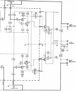
The circuit is PNP input driving a darlington NPN with an NPN TO220 output. DIagram attached.
Is it possible to have the PLH in bipolar equivelent? perhaps with less then 1A bias and a PS of 17V. My speakers could play v loud as it is with the mere 3 W or so and I need to run it cool as in the morning my room is quite hot with Singaporean sun shine...!
Tks and best rgds
William Lee
😱
hi Nelson and all,
I am half way modifying my Mcintosh C-28 head phone amplifier to drive Altec 755A. With all capacitors replace esp the input cap using the Russian green PIO, removing the regulated power supply to have a B+ of 17V etc, the sound is decent, though I still prefer my ECC803S-2A3C amp.
The circuit is PNP input driving a darlington NPN with an NPN TO220 output. DIagram attached.
Is it possible to have the PLH in bipolar equivelent? perhaps with less then 1A bias and a PS of 17V. My speakers could play v loud as it is with the mere 3 W or so and I need to run it cool as in the morning my room is quite hot with Singaporean sun shine...!
Tks and best rgds
William Lee
😱
Attachments
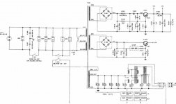
C 28 regulated PS
The Mac C 28 P transformer is robust and could supply lots of power... I might eventually add the 12V secondary for the head phone amp with the 6.3V secondary for the lamp to get bigger output, but of course I need to use TO 3 bipolar such as MJ 15003 with heat sink.... I suspect the 13.5V winding is good for 5 A though only rated for 2A, while the 6.3 V is rated for 4.5A but definately more, as after long use the PT is barely warm...
Best rgds
William Lee
Attachments
Hi
What do you think about using PLH/JLH design as power folower like this :
http://img100.imageshack.us/img100/9770/phasespna3.png
with aikido gain stage :
http://img178.imageshack.us/img178/2659/powerampqv0.png
thx
What do you think about using PLH/JLH design as power folower like this :
http://img100.imageshack.us/img100/9770/phasespna3.png
with aikido gain stage :
http://img178.imageshack.us/img178/2659/powerampqv0.png
thx
- Status
- Not open for further replies.
- Home
- Amplifiers
- Pass Labs
- Plh