Variac said:Couldn't we just have 2 holes for the cap near the edge of the board and then leave the leads on the cap pretty long and then bend the ends of them 90 degrees to fit through the board?
I other words the cap is sticking sideways off the board? If the holes are pretty close to the edge, then the leads really wouldn't have to be that long...
A very good idea indeed 😀 Could the cap be mounted on the backside of the pcb? Ie. between the heatsink and the pcb? Or would the environment be too hot
 ?
?Mounting C4 behind the PCB is not a good idea. Not enough space and it does get very hot back there.
I still think that mounting C4 in the L&R rear corners is best. Take a look at the pictures I have previously posted of the inside of the Hafler chassis. There is very little room between the front side of the PCB and the transformer and filter caps.
Now, we may have to use a different transformer which may be smaller or a toroidal mounted on its side -- which would open up more room. Also, we may not use the filter caps in the Hafler and use newer caps with a smaller form factor. Nelson mentioned a CRC supply of two sets of 30K uF separated by a 0.5 ohm resistor. How much space would all of this require?
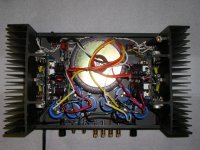
Here is another picture of the interior of a Hafler. This picture shows a modified amp with Musical Concepts PCBs, a toroidal transformer, and two bridges and two sets of filter caps. You can see how the space gets used up.
However, even with this stuffed chassis there is still some space in the back L&R corners where C4 could be located. At C4's point in the circuit the signal is that going to the speakers so a little extra wiring is OK. Also, the signal is strong so charging pulses from filter caps should not interfere.
You can also see the location of the fuse holder for each speaker output. If these fuses are not used the holes left by removing the fuse holders could be used to mount P2.
Hope this helps.
I still think that mounting C4 in the L&R rear corners is best. Take a look at the pictures I have previously posted of the inside of the Hafler chassis. There is very little room between the front side of the PCB and the transformer and filter caps.
Now, we may have to use a different transformer which may be smaller or a toroidal mounted on its side -- which would open up more room. Also, we may not use the filter caps in the Hafler and use newer caps with a smaller form factor. Nelson mentioned a CRC supply of two sets of 30K uF separated by a 0.5 ohm resistor. How much space would all of this require?
Here is another picture of the interior of a Hafler. This picture shows a modified amp with Musical Concepts PCBs, a toroidal transformer, and two bridges and two sets of filter caps. You can see how the space gets used up.
However, even with this stuffed chassis there is still some space in the back L&R corners where C4 could be located. At C4's point in the circuit the signal is that going to the speakers so a little extra wiring is OK. Also, the signal is strong so charging pulses from filter caps should not interfere.
You can also see the location of the fuse holder for each speaker output. If these fuses are not used the holes left by removing the fuse holders could be used to mount P2.
Hope this helps.
Attachments
My idea with the cap sticking out from 2 holes might work either way depending on how it ca nbe laid out.
1. Have the cap sticking out towards the rear corners but attached to the board
or
2. run wires to the cap from the same holes.
1. Have the cap sticking out towards the rear corners but attached to the board
or
2. run wires to the cap from the same holes.
It seem that the only person with an Adcom amp is Nelson.
Nelson, you were going to get the dimensions for us.
I would request the dimensions of the existing board, and how much bigger a board could be that would also fit. Of course we also need the locations and spacing of the mounting holes...
If the Adcom makes it toocomplicated we'll have to drop it, but let's give it a go....
in post 83:
http://www.diyaudio.com/forums/showthread.php?postid=843439#post843439
Dick suggests a good place to put the cap.
I think I have an idea!!!!
There is no requirement that the board stop at the rear bolt hole. The board can be longer toward the rear PAST the bolt hole. It will be bigger than the stock board, but still fit in the chassis, almost touching the rear chassis panel in the photo that says "Caution!" Then the cap gets mounted in the opposite direction as the other components on the backside, but the cap isn't in the hot area between the flanges of the heatsink.This keeps it well away from the power caps as suggested by Nelson and in the little area suggested by Dick. This gives more room for other caps and components also. Kari: please tell me if this is clear!
OK. I'll do as sugested. Just to make sure, how wide should the board be now? As soon as we get the Adcom dimensions we should be able to rap this up pretty quickly.
Thx,
Kari
Thx,
Kari
Here is the photo of the interior:
http://www.diyaudio.com/forums/showthread.php?postid=841565#post841565
IT looks like the board can be extended in both directions, ie front and back equally if we want. Of course there has to be clearance front and back since the boards are identical and not mirror images. IF we really run into problems we could make mirror image boards, but that's an additonal expense.
These boards are getting big, but I don't see a way out if we are using Poly caps. I don't think they are going to work on the Adcom... but let's not give up yet!
Of course we could use Blackgates only , and then things would be a lot more compact, BUT with them being no longer made (again!)
I don't think that's smart.
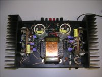
Yes, the board can be extended in both directions, but both of the front two corners do not have the same space as is in the back two corners. In picture below you can see that the front right corner has the AC cord and switch and power fuse, plus the little circuit that makes the switch light (or yellow indicator light) blink when one of the thermal sensing switches opens up.
However, the left front corner has about the same amount of space as the back two corners.
Therefore, the board for the right channel could extend towards the rear and then, when it is turned around for the left channel, it could extend towards the front.
Do you guys think the thermal sense switches should be retained? You can see the amount of space they consume. These two switches are in a loop that continues the AC from the power switch to the transformer and if one opens up from overheating it turns off the AC to the amp's power transformer -- a useful safety feature.
Do C3 and C4 need to be mounted on a PCB? They are in series with the output to the speaker and could be mounted in the two rear corners with some strapping. Wiring could extend from the proper locations on the PCB to the capacitors and then on to the output jacks.
I did a mock up of the PCB as drawn and it would fit nicely on the Hafler heat sink if the space presently alloted for C3 and C4 was no longer required.
Attachments
OK Dick, I understand your points, and your input is keeping us honest here! 😉
BUT a very important point:
In order to make the board snapable, we need to have 2 board layouts on one big board with a snappy line between!(so they can be used without snapping in the Adcom) SO they can be Symetrical!!!!! so the boards can be designed so the Hafler left board has the caps on the right and the right board has the caps on the left.
So it is easy to have the caps at the rear corners of the amp.
Perhaps a compromise is to have space on the board for Blackgate sized C3 and C4 caps, and if you want to use the bigger ones, then run wires from the cap holes on the board to the caps mounted as Dick suggests.
here is the link to the Adcom photo.
http://www.diyaudio.com/forums/attachment.php?s=&postid=844947&stamp=1139879200
It shows the combined 2 boards need to be pretty small and Symetrical!!!
So the board is are more likely to work in the Adcom if they are small and symetrical! So as described above, small Blackgate caps or remote caps as suggestd by Dick make it a lot smaller.
The combined board unsnapped, as it will be used by the Adcom, can have its Adcom holes drilled to shift it to the right in the Adcom so the center of the board is offset to the right. This would give more room for the board in the Adcom because there is a lot of room on the right, about an inch it apears The board could about a quarter inch bigger on the left also. Bigger also front to back (equalivent to bigger top and bottom on the Hafler)
I think we need Nelson to cut out some pieces of card the size of the stock Hafler boards and see if 2 taped together will fit into the Adcom. If not maybe he can tell us how they need to be shortened...
I wonder how much space is available under the PCB as mounted in the Adcom? Perhaps that space could be used to hold C3 and C4?
You are correct, we need a hands on mock up with an actual Adcom.
Dick
You are correct, we need a hands on mock up with an actual Adcom.
Dick
IF we get a real compact layout, then a lot of the board size can be blank, just to give us the mounting hole areas. This would mean that there isn't a requirement for parts clearence in these areas.
I believe that if we get this board designed and tested, there is a possibility that Nelson will try to publish it, with instructions.
Of course I can't speak for him 🙄
This would get a lot of publicity for the boards, and get the word out to lots of people that own one of the amps. If this happened, we would eventually sell lots of boards, which could really benefit DIY Audio, and also benefit the owners of many, many old , unloved, and not state of the art amps. So, I think the buy will start out slowly but build to a constant volume that will eventually set records!
If we run into serious design problems, having two different board designs might become the best, one for each amp. If they are symetrical, I think we could make the Hafler boards big enough to hold even the big caps on the rear of the boards into the rear corners. But having universal boards was the original challenge, so let's keep trying!
geez, sorry I didn't where this thread was going!
I have an Adcom 555mk2 in the garage with the cover just 'sitting' on. It's fully operational so I don't plan on doing this mod(or taking it apart) but I would be happy to get close and personal with a camera and a ruler.😉
Life's commitments keep me ridiculously busy so have a bit of patience and I'll post what I find. In the meantime if you could summarise exactly what you are looking for that would help.
regards...
Hi!
We would need the dimensions of the board in the Adcom, as well as measurments of the mounting holes. Also a good thing to know would be how much clearance we have to left, right, up, down and behind the original Adcom board.
Your help would be greatly appreciated!
Thx,
Kari
We would need the dimensions of the board in the Adcom, as well as measurments of the mounting holes. Also a good thing to know would be how much clearance we have to left, right, up, down and behind the original Adcom board.
Your help would be greatly appreciated!
Thx,
Kari
As Nelson mentioned C3 and C4 might pickup noise and the key to prevent that would be to mount those caps on the board. As it is now i'm planning on using a ground plane to help fight against noise.
What about this idea? We put connection pads on the pcb for C3 and C4 and then use a shielded cable to connect those to the pcb and the shield would be connected to the ground plane? Now you could place those caps whereever you wanted and stil have protection against noise. Comments?
/Kari
What about this idea? We put connection pads on the pcb for C3 and C4 and then use a shielded cable to connect those to the pcb and the shield would be connected to the ground plane? Now you could place those caps whereever you wanted and stil have protection against noise. Comments?
/Kari
I thought that Nelson was specifically concerned with getting C3 and C4 too close to the Power supply caps.
If the boards are symetrical and extended to the rear, and the caps are mounted on the back of the boards, then they are in the two rear corners of the chassis and away from almost everything.
OK, great news; now we will have mpmarino opening his Adcom for us. He should just leave it open so we can ask more questions! This will be a huge help, as we should save Nelson for circuit related questions! (although this whole Hafler/Adcom interchangability issue was his idea!!!) 🙄
My suggestion is to wait until we get the dimensions of the Adcom board to decide how to go. Possibly we will give up on the interchangibility plan if the Adcom is too different. The remote caps will also be a lot easier to impliment with symetrical boards, in that the leads to each cap for each channel will be the same length and pass identical components, ensuring that one channel doesn't sound different than the other... Another upgrade from the stock Hafler (the Adcom already has a symetrical layout)
Seems like the C3 & C4 caps could be remote mounted between each Adcom outermost output board and inner output board...
How to work with the Adcom output boards is another issue. Can we just unsolder the (E) mosfets and put in new ones?
How to work with the Adcom output boards is another issue. Can we just unsolder the (E) mosfets and put in new ones?
Guys,
I didn't have time to get specific with measurements on my 555mk2 but a quick peek made me wonder if it is worth it. First off, I have a MK2 whereas the pic previously linked to is a series 1. It seems different. Mine would require diasaaembly to get truly accurate measurements as the rear of the board is shrouded. Also, mine has 4 mounting screws where the above pic has 2 that I can see. My point is that mine, being a '2' is just one of the models of the 555 and how the heck can you make a board to fit 2 different adcoms and a hafler?!
There is, I suppose, the possibility that the boards 'could' physically interchange. If you want me to proceed I would have to disassembe some of the amp to get you good numbers, which I will do if you really want me to. I do have a feeling that the mk1 and mk2 do have a different mounting scheme though... too bad I sold my other..it was a series 1.
lemme know
Let me make a suggestion here to narrow the scope of this project to make it just for the old Hafler amps. I'm not an expert by any means but it seems to me that any time I have seen the insides of an Adcom amp they were different. On the other hand, the old Hafler amp series were all identical inside.
The Hafler DH-200/220/XL-280/P-225/P-230 all use the same style heat sink and their internal chassis measurements are all about the same, plus they all have the same power transformer. We know the XL-280 has booster windings on its PS transformer but they can be ignored for this project and the main windings provide the same AC voltage as the others.
Given the fact that so many Hafler models will work with this project and that there surely are many more of them than Adcoms, it seems to me that you guys might make it for just the Hafler. Later, if the project works OK and as interest in it increases, you could branch out and revise its PCB for certain Adcom models -- depending on how many Adcom owners express an interest.
What do you think?
Dick
I don't know if there are more DH-200's than 555's or not.
At its peak, I think Adcom may have been moving a couple
thousand per month. (thumbnail calculation)
At its peak, I think Adcom may have been moving a couple
thousand per month. (thumbnail calculation)
- Status
- Not open for further replies.
- Home
- Amplifiers
- Pass Labs
- Plh Retrofit to Hafler/Adcom