The input of the amplifier benefits from seeing the low impedance of the RF capacitor.
Locating the RF capacitor near the +IN input is good.
I add another RF filter at the input socket. This uses the output impedance of the Source and the impedance of the interconnect to create a 2pole passive filter. R+L C
Recently I tried a slightly different arrangement using an XLR socket for an unbalanced input.
Signal Hot to Signal Return - 47pF direct on the back of the terminals.
Signal Hot to Pin1 - 47pF direct on the back of the terminals.
Signal Return to Pin1 - 47pF direct on the back of the terminals.
All three ceramic caps have very short leads and form a triangle around the terminals.
Pin1 is connected to the XLR shell and the shell is electrically bolted into the chassis.
I cannot hear, nor measure, any adverse effects.
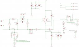
Increase R4 to 27k to match R7. This reduces output offset.
You can trim R4, to precisely set output offset to zero mVdc.
C1 < R5 * C4 / sqrt(2) / R4
Your value of 2u2F complies.
But you may be able to hear a slightly stronger very low frequency bass if you increase to 3u3F or 4u7F
1k*220u/1.4/27k = 5u7F
1uF, 1u5F, 2u2F, 3u3F and 4u7F all comply. Worth experimenting to find out if you hear any difference.
If you hear absolutely no difference in the passing signal with the 1uF cf the 4u7F then just fit 1uF with that combination of amplifier and speaker.
About the smd resistors, how much of a quality difference is there between thin film and thick film resistors. For which resistors do I need thin film resistors here. Between metal film resistors and thin film resistors, which ones are better, accounting for the fact that the smd can get real close to the pins while metal film ones cant, specially for the feedback path.
THT is better pretty much in every possible way... But for chipamp SMD are totally fine. Stuff ive heard miht be snakeoil tho..
smd Thin film is metal film. Thick film is metal oxide.
Some Thin film are specified to very tight tolerances and tempco.
It would seem that the technology applied to the best of smd Thin film is generally at least as good as through hole and often better.
But that comes at a cost.
I would put price ratios as follows
smd Thick film @ 1unit, smd Thin film @ 3units, smd thin film superquality 30units
That puts super quality out of my price range.
Last edited:
the super quality ones are out of my price range also. Most of these are 0.1%, with 5ppm tc. the normal thin films are either 25ppm or 50ppmm with 0.5% tolerance, while most of the thick films are 100ppms. The 1206 in thin film are all very expensive while 0805 has cheap ones too. Some of the low tc advantage is lost because of lower power ratings of 0805 thin films. I think the tighter tolerance also wont make too much of a difference in sq.
I think in this design, R1 (1M) and R3 (2k2) can be easily changed to thru hole without compromising on sound quality. I need to basically take a call on the three feedback resistors (r4, r5, r7), (I prefer to use smd for these), whether to continue using 1206 thick film or use 0805 cheaper thin film ones. Any suggestions?
I think in this design, R1 (1M) and R3 (2k2) can be easily changed to thru hole without compromising on sound quality. I need to basically take a call on the three feedback resistors (r4, r5, r7), (I prefer to use smd for these), whether to continue using 1206 thick film or use 0805 cheaper thin film ones. Any suggestions?

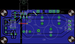
What about not using the ground plane for the R2/D1/D2 to pad5 connection? A simple trace might be better.
r2 bottom end is already at the power ground. pad5-pad6 connects the two power ground pours.What about not using the ground plane for the R2/D1/D2 to pad5 connection? A simple trace might be better.
1. Disconnect pad5 from the power ground
2. Trace from pad5 to R2.
3. Combine the two power grounds into one.
2. Trace from pad5 to R2.
3. Combine the two power grounds into one.
Im not quite sure if this was an improvement on the ground pour.
Now you inject all the PSU interference from the negative power rail to the input circuitry.
I myself like to "inject" the "ideal zero" everywhere around the sensitive parts of the circuit...
Do we have more opinions about this?
Now you inject all the PSU interference from the negative power rail to the input circuitry.
I myself like to "inject" the "ideal zero" everywhere around the sensitive parts of the circuit...
Do we have more opinions about this?
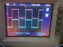
I made a one channel build with a toner transfer pcb (as in post 150) , haven't added the thiele network yet, input cap is also a 2.2u polyester, trafo is EI 15v. Checked for oscillations on the scope, it looked ok and connected my overnight sensations speaker to it. It sounds really good, much better than the topping tp20 i am using currently.
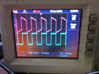
I have taken some scope pics and attached them here. I havent attached a load to it (dont have a big 8 ohm resistor, will get one and give it a try), feeding it with a square wave from my siggen (it only gives sq wave or pwm wave, no sine or triangle). Looks ok at 1khz, but not all that good at 20hz or 20khz, is there an issue with the lf or hf response? Meantime i will try to burn some sinewave cds and try it out.
the pics are a bit blurry, didnt notice it on the mobile. the first is around 1khz, second is 20khz and third is 20hz. Blue is input (scale=200mv) and red is output (scale=5v).
Attachments

Last edited:
Is OK.
Increase value of input cap if you want better LF responce.
Congrats for your new amp!
Yeah, thats on my to do list.
Thank You, it wouldnt have been possible without your help. Gained a lot of useful knowledge also, which will help me in future designs also.😀
5Vpp across 8r0 is about 780mW. You don't need a big resistor as a test load.
Use two 15r 600mW for a net 1.2W 7r5
or
use three 24r 600mW for a net 1.8W 8r0
sinewave and squarewave testing around the 4Vpp to 5Vpp is quite normal.
You scope pics also look quite normal.
Use two 15r 600mW for a net 1.2W 7r5
or
use three 24r 600mW for a net 1.8W 8r0
sinewave and squarewave testing around the 4Vpp to 5Vpp is quite normal.
You scope pics also look quite normal.
- Status
- Not open for further replies.
- Home
- Amplifiers
- Chip Amps
- please review this pcb design