MJK said:The equation for the CSA at the bottom of page 3 is shown below.
S0 = (p c Sd^2 DZ DR Re) / (BL)^2
I have set the scale factors DZ and DR to produce an area that will lead to a particular SPL response curve. This curve is the goal that I use to design TL enclosures. Different people might have different design goals which would require different values of CSA. In general the larger the CSA the higher the bass response. I have selected what I consider to be a good compromise between bass output and enclosure size. Other people might make different trade-offs and recommend different CSA values. This is only my recommendation. To each his own.
Greets!
?? Understood and IMO didn't say or imply anything derogatory or otherwise WRT your design choices in any of my responses, just merely remarked that with this formula I got a much larger value than I do using the formula on pg. 13, ergo more bass and harmonic output as you note, which means more stuffing will be required for a given alignment.
The equation on page 13 is the same equation as shown above but with Sd pulled to the left side to form the ratio I like to use when describing a TL. If you divid both sides of the equations above by Sd you will get the following.
S0/Sd = (p c Sd DZ DR Re) / (BL)^2
I tend to express the CSA of a TL in terms of a ratio with the driver cone area Sd. So the equation above yields S0/Sd = 2.872 on page 13. Since SL/S0 = 1 for the example, SL = 2.872 Sd. I don't see any error, what am I missing?
The "/" sign indicates a ratio between or a division of one variable by another. While you may not agree with my alignment, and you may have a better method of your own, I do not consider anything above an error. So far the feedback I have recieved about TLs designed from the tables has been very positive.
Frankly, I haven't given any thought to your alignments beyond browsing the info enough to recommend using them as a good first approximation and try to answer folk's Qs as best I can with the info given me. Since this apparent discrepency has only come up in private AFAIK and your stated lack of time to respond to individual requests, I figured I had a better chance of getting it resolved on-line.
In all my decades of dealing with compression, room, etc., ratios I've never seen the '/' used to express them, only a ':', but in a Google search I see it's used in math formulas.
Anyway, since you confirmed the two will yield the same answer and with the formula explanation, I finally figured out that I did the Sd^2 unit conversion incorrectly in the pg. 3 formula, calcing a 10x too large an area, so my math ignorance got me twice.
Still, a lot of folks read my posts before you responded and didn't correct me, so combined with the times I've been asked about this, I feel that's enough justification to revise the doc with a bit of clarification.
GM
In all my decades of dealing with compression, room, etc., ratios I've never seen the '/' used to express them, only a ':', but in a Google search I see it's used in math formulas.
A ratio is nothing more then one number divided by a second number. The " / " symbol is a standard method of denoting division on any computer. If you are programming, using Excel, or just typing a text expression in a document with a division in it the " / " is the only option as far as I can tell. I don't know how one would even enter a " - " sign with the dot above and below to denote a traditional division operation. So I guess I am not too motivated, and I don't even know how, to change my style which appears in all of my documents, all of my e-mails, and all of my postings where a division is expressed.
Still, a lot of folks read my posts before you responded and didn't correct me, so combined with the times I've been asked about this, I feel that's enough justification to revise the doc with a bit of clarification.
If somebody has not used a spreadsheet program and entered a division using the " / " symbol, then I guess I can understand the confusion. But if the individual has done even the most primative math operations on a PC this should not be that confusing, this has to be a very small group of readers. If it is confusing and they have not asked for clarification, then they are only short changing themselves. There is only so much I can do to accomidate everybody, I have to assume some minimum level of basic algebra and computer math. Some people may fall through the cracks.
I finally had a chance to sit down with the alignment tables and some driver specs and a calculator. I modelled a 20 hz straight line with a Dayton 15 inch driver, fs 19 hz.
The sample problem in the alignment tables calculates SO/SD = 2.872. My results are much closer to 7. The original Jensen Transflex, which is the basis for my current project is much closer to 1.
Are my calculations typical or am I doing the math wrong? SO/SD = 7 makes for an uncomfortably fat CSA, especially for a low tuned line with a 15 inch driver.
I have seen figures between .75 and 1.25 x SD for estimating CSA, so my results are a bit startling to me...
Opinions?
Ok, since I posted last I tried a different Dayton driver with wildly different results. The Series II that I tried first had a huge CSA while the Quatro, which I tried later and is coincidentally on sale at partsexpress.com yielded a CSA lower than SD. It seems as though Re is a major factor in this equation and I'm not really sure why Re has any relationship to CSA at all. Re makes a big difference in the two drivers listed below, anyway.
Here are the specs that are required for the alignment tables.
Series II
Sd - .086 m
Re - 8
Bl - 27
Qts - .34
Quatro
Sd - .0814 m
Re - 3.45
Bl - 17.5
Qts - .41
If you need more specs, they are part numbers 295-130 and 295-560 at partsexpress.com, or just let me know which specs you want and I'll find them. From the info I have derived, if correct, I am very interested in purchasing the Quatro before the sale ends.
just a guy said:Opinions?
Greets!
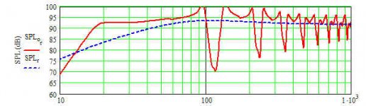
Apparently, you've 'fallen through the cracks' 😉 since I get 0.88213 and this plot with 0.1 lbs/ft^3 stuffing density:
GM
Attachments
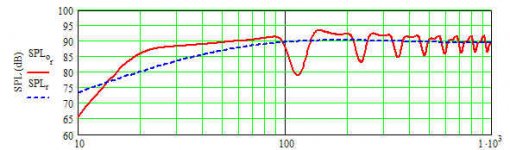
Thanks for the charts, they are very informative and the Quatro in particular looks very intriguing. Just to be clear, those were both done with a 20 hz line with CSA = 0.88213 x Sd, right?
If this is the case I really need to brush up on my math skills, but at least I was really close on the Quatro.
In any case, the CSA listed above is almost exactly what I had planned and even had the wood cut. The wood got a bit wet but it might be salvaged yet...
If this is the case I really need to brush up on my math skills, but at least I was really close on the Quatro.
In any case, the CSA listed above is almost exactly what I had planned and even had the wood cut. The wood got a bit wet but it might be salvaged yet...
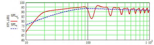
You posted that last graph while I was typing, lol. I like the first Quatro graph a bit better, it extends down to 20 hz a bit more gracefully. So comparing the 2 Quatro graphs, it looks like slightly larger CSA helps out the bottom of the FR graph.
Regarding the second graph, which is the first Quatro graph - corner loading would keep this response flat down to about 18 hz, yes no?
I wasn't expecting 95 db sensitivity from a straight line. I might taper it a bit to mass load and hit 15 hz flat, I can afford to lose a couple db's.
I think I will buy the Quatro before the "Special Price" ends.
I was also looking at the Dayton Classic 4 ohm, I had it modelled in the same line for me awhile back. It was much stronger in the low end but much less sensitive (flat from 20 up at 88 db) in this particular line.
Greets, part deux! 😉
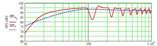
Actually, it looks marginally better at both ends before the 3rd harmonic dip and increasing CSA will increase gain up to a point of diminishing returns. At 2x the S2's alignment CSA, there's considerable gain down low where its needed if the room's construction is 'leaky', like mine.
Boundary loading is room layout, construction dependent, so without actual measurements about all I can say is that typically you get 3-4 dB extra down low instead of the theoretical 6 dB.
Yeah, the driver's high inductance puts a pretty big hump in the midbass and mass loading will lower Fb, but this compromises excursion higher up where you need it more, so 'robbing Peter to pay Paul' might bite you WRT SQ and maybe even driver damage.
GM
Attachments
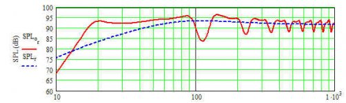
Your interest in my humble project is appreciated. Wow, that last FR chart looks really good, it is very similar to the Dayton Classic 4 Ohm I had modelled for me awhile ago in this line, exept the Classic line was about 6 db down.
I know this is kind of backwards, but I selected my form factor before driver selection. Since the wood is already cut I can't change much but my line is very slightly different than what you modelled. My line is actually 171 inches, not 168 and CSA is about 128 sq inches, or about .97 x Sd. I do not plan to add any stuffing at all. This sub will be crossed over between around 50 - 80 hz so I don't care much about the top end.
I am mainly concerned with LF extension that is at least flat to 20 hz in my room, preferable 3 - 6 db louder at 20 than 80 without equalization.
The slight differences in my line vs what you modelled would probably help the bottom end a bit but probably not enough to satisfy my FR curve desires based on your estimate of 3 or 4 db corner loading and room gain.
I don't really want to start at the beginning and make a box twice as big to accomodate your last FR graph but I also don't want to lose 6 db with the Classic.
It's the old SPL vs LF extension dilemma.
I think I'm sold now, that's about as flat as it gets from about 20 -40 which is my target area and corner loading is going to boost it nicely.
I'm assuming we are still talking about the Quatro, not the Series II. Time to get the credit card out.
I'm assuming we are still talking about the Quatro, not the Series II. Time to get the credit card out.
By the way, do you care to speculate on how a Jensen Transflex loading alignment will affect this last FR curve? And what was the driver offset in that graph?
I know it can't be modelled and I'm still a few weeks away from the answer, but I'd like an opinion to tide me over.
I know it can't be modelled and I'm still a few weeks away from the answer, but I'd like an opinion to tide me over.
Greets!
The transflex is an attempt to use both sides of the driver's output to increase gain over 'x' BW and is flawed in that the driver is in the wrong position to work properly, so I speculate that the FR will be too uneven to be of use without significant EQ and that all of the additional gain will need to be attentuated, and then some due to the extreme notching that will occur. Apparently, Tom Danley got it figured out in his recent Tower Of Power sub invention.
The driver position is per the Classic TL chart recommendation, so 171*0.349 = ~59.68" down from the closed end.
GM
The transflex, billed in '52 as a bass reflex/tl is kind of the inspiration for the project with the Tower of Power an interesting side note. The added gain would be welcome down low and the transflex was never intended to be used above 45 hz anyway.
My thinking was that mounting the driver in classic tl position (.25 - .33 down the line) but inside the box, like the Tower of Power would reap the benefits of the transflex with added smooth response on the top end.
We'll see. Regardless, I think I owe it to myself to try 3 different mounting locations, as you modelled, transflex location, and the Tower location.
GM, I have a question about the graph you made for me in post 34. I saved all the charts you made, and just for my personal notes I was wondering if that particular graph was modelled at .97 x CSA or the same line as before (.88) but without stuffing. I wouldn't ask so long after the fact, but in another post I think I noticed you keep records of these graphs you do for people.
Just to let you know, I purchased the driver (15 inch Quatro) and it was delivered this week, based on the models you made for me. Thank you.
Just to let you know, I purchased the driver (15 inch Quatro) and it was delivered this week, based on the models you made for me. Thank you.
- Status
- Not open for further replies.
- Home
- Loudspeakers
- Subwoofers
- please help with MJK's alignment tables