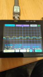
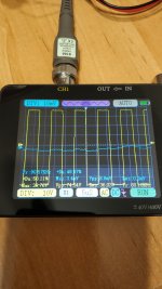
Great! It's not dead anymore but you could still have a power problem. If you have that scope handy, then can we see the Drain voltages of Q208 and Q209? With no input signal, they should be square waves and have amplitudes equal to the rail voltage and be inverses of each other. When you apply an input, the duty cycle should change and the two drains should remain an inverse of each. If they look good at all power levels then the problem is likely somewhere else.

You guys are amazing!
I tested the drain with the oscilloscope, it comes out as a square wave, 10x and 1x images. I didn't understand about the reverse signal, is it necessary to use two tips? this oscilloscope only comes with one tip, but I can get another one.
I was using the headphone output of a smartphone to test the audio, and as the input voltage comment of RickRay made me wonder if it wasn't enough, I took a radio module from the stereo. It is clear that the line output of the module has more signal, now the volume is usable at less than 50%. Great success! however, with the potentiometer at minimum there is some very low sound, as if some audio is sneaking in that the potentiometer does not control, it's very low but it's there.
Also another thing noted, is when I power on the amp, the sound comes with a delay, you hear the click of the relay and then appears the sound, seems normal, but previous to the sound appears there is a "high pitch sound" like "plif", like the speaker activation, some capacitor should not be involved on this?
Attachments
I repaired a BASH subwoofer amp on a SVS PB10-NSD. It had bad low voltage regulators in it. They needed heatsinks from the factory, but they cheaped out. I also tested all the capacitors in it while I was in there. They all had VERY high ESR, they were also all VERY low quality capacitors. I am not a recap person, but in this case, they all needed to be replaced. Most of these Class D sub amps are made in China with the cheapest parts that can be found.
Thanks RickRay, over the past month unsoldered several of the capacitors and according to the capacitance meter and with a small LCR-P1 indicated around 1% or 2% loss which seemed pretty good, if it is true that those with voltage regulators were around 2,x to 3%, but the impedance was still low. These days I bought a tester to measure them on board without desoldering, a MESR-100 I do not know if it is very reliable, but I will give them all a check in case appears one with high values.
No. You don''t need to bother with another probe. The drain that you plotted looks fine. If the other drain looks like this drain meaning 50% duty cycle and the same amplitude then your power stage looks good. If you have significant volume then the output stage is working.
I was not able to distinguish between the two drains so I thought I was doing something wrong. The power with the radio module is good.
Do you also think that the power capacitors may be what is causing the “plif” sound when turning on the subwoofer and that minimal volume escaping from the volume control? I was thinking about what RickRay commented and perhaps from my ignorance, I thought about the power capacitors in the c314 and c315 that are on the main board, but of course, I forgot about the big C302 of 80v 4700uf "panic one", the C310 that is in the 10v line and those that are on the amplifier board C233 of 80v but 1000uf also and C232 of 25v, all of them are power capacitors? not to start changing capacitors without knowing why. How does it affect the low ESR, I think all the capacitors I have around here as spares are normal ones, should I go to the special audio ones?
Do you also think that the power capacitors may be what is causing the “plif” sound when turning on the subwoofer and that minimal volume escaping from the volume control? I was thinking about what RickRay commented and perhaps from my ignorance, I thought about the power capacitors in the c314 and c315 that are on the main board, but of course, I forgot about the big C302 of 80v 4700uf "panic one", the C310 that is in the 10v line and those that are on the amplifier board C233 of 80v but 1000uf also and C232 of 25v, all of them are power capacitors? not to start changing capacitors without knowing why. How does it affect the low ESR, I think all the capacitors I have around here as spares are normal ones, should I go to the special audio ones?
- Home
- Amplifiers
- Class D
- Please, help to fix my Class D Kenwood Subwoofer