Thanks RickRay, but on the board view, the pin 1 of the main board is the pin 4 on the amplifier board, there is not a continuity point of -12,4v on the CN5 P1 and CN2B P1, on the CN2B it's -12,4v present, on the CN5 P1 not, maybe it's a fail on the schematic?
Attachments

You have -12V on CN5 on the main board. I'm not seeing a CN2B. I see the ribbon going to CN05 on the amplifier board. Start by checking for -12V in pin 1 of CN5 on main board. Then trace cable and check of -12V on the other end.
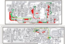
Yes, you have -12V from IC 304. I'm trying to determine if the output MOSFET's are recieving -12V. The schematic shows -12V, then shows 12V. Not sure which is right. But, it is showing a path from CN5 to CN05 on the amplifier board that should be recieving -12V. That -12V is shown going straight to two of the MOSFET's. That would make more sense, easier to reach reach 50W with 24V across the outputs, push-pull.
Thank you for your help and effort 🙂, on the CN5 of the mainboard:
P1: 0v
P2: 4,98
P3: 0
P4: 74,5v
On the amplifier board CN5,
P1: 74,5v
P2: 0
P3: 4,98
P4: 0v
On the schematic is not coherent indicating P1 -12,4v on the amplifier board when this come from the 80v main capacitor of 4700uf on the mainboard.
Just one question, maybe I'm feeling stupid, but, it's correct to measure earth on chassis not?
Not a dumb question, I'm not sure myself. Let me lok at schematic some more. Are you sure it is reading 74.5V and not 74.5mV? Is the 4700u you are refering to C233?
OK, I'm seeing the 4700uF/80V capacitor on the main board. It isC302 and just below that I see the chassis connection through a 100 ohm resistor. I think you would be fine measuring ground at the chassis. No current flowing to speak of through a meter, it would be close enough to troubleshoot.
I do not know enough about the amplifier section to be of any help other than checking for applied voltages. It looks to me like you have 74.5V, 12V and -12V applied to the output section. How that works is beyond me.
Looks like Q204 should have 74.5V on the collector and +12V on the emitter. Looks like Q202 and Q203 somehow drive Q204.
The resistor 245 is a ceramic one, 0,1 ohms and 3w, this do continuity with that, both sources are then joined with the "earth" by that resistor? this is making me mad, I can't figure how that works...😵
Fully tht class d what a unicornHi, I've been tinkering with this subwoofer for over a month, and I can't get it to sound right.
I have desoldered about half of the components of the boards and I can not detect what is happening....
It is a Kenwood SW-505D subwoofer. It sounds very distorted, you have to select near full the volume to make it sound something low like a trapped fly...prf prf prf prf prf prf prf
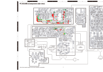
I'm just an amateur without much knowledge, but I think I put my heart into it. I think, that the failure is in this board... any help will be appreciated, thank you!
The voltages on the HIP4080 are:
P1: 11.63v
P2: 12,14v
P3: 0,34v
P4: 0,011v
P5: (not soldered on board) variable around 0,520v with the volume at 0 and around (oscillating) 4,80v at max
P6: 6,21v
P7: 9,27v
P8: 5,18v
P9: 5,18v
P10: 11,64v
P11: 0,028v
P12: 0,028v
P13: 11,26v
P14: 0,011v
P15: 12,14v
P16: 12,14v
P17: 0,011v
P18: 0,39v
P19: 0,009v
P20: 0,010v
IC3
P1: 9,90v
P2: 6,57v
P3: 6,59v
P4: 0v
P5: 5,814v
P6: 5.814v
P7: 6,051v
P8: 12,13v
IC2
P1: 6,059v
P2: 6,059v
P3: 6,055v
P4: 0v
P5: 6,059v
P6: 6,059v
P7: 6,21v
P8: 12,13v
IC1
P1: 0v
P2: 0v
P3: 0v
P4: 0v
P5: 6,103v
P6: 6,059v
P7: 5,161v
P8: 12,13v
Beyond me also.The resistor 245 is a ceramic one, 0,1 ohms and 3w, this do continuity with that, both sources are then joined with the "earth" by that resistor? this is making me mad, I can't figure how that works...😵
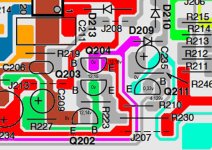
It seems that you can't believe the schematic completely. It has some inconsistencies. It is clear that the 4808 is powered by 12V above the negative power rail. The R245 is a current limit resistor that must go to the negative power rail. At some current in R245, the voltage triggers an SCR made by Q202 and Q203 which is referenced to the negative power rail and it turns on Q204 which drives the shutdown pin of the 4808 to that same 12V rail. I don't see where a negative 12V supply is needed in this part of the circuit so its label is probably an error.

Thanks James, will wait then until the arrival of the replacement for the hip4080. I just got a pocket oscilloscope, I don't know how it works yet, far from power it on 😆, in case it can be of help.
I thank you all for your help, the truth is that I have made more progress in the last two days than in the whole of last month.🍻
Hi all, the hip4080aipz has arrived, any recommendation before soldering it? I can make measurements of values between all the pins of the newly arrived chip in case it is useful for more colleagues sometime, to compare measurements with a new one. Any advice from which pin to make the measurements? 14 or 17?
Hello, partially good news! fitted the new HIP4080, the sound now is clear, no distortion, although I still need to get the potentiometer to the middle to be heard, between the minimum volume and 50% I can hear almost nothing, could be a problem in the preamplification? Is there an easy way to measure the output power? seems like a 5W amp.
On the other hand in this case I was comparing the broken HIP4080 IC with the new one (unsoldered), in case someone else has something similar, the main difference I found was between the reading in diode mode of pin 1 and pin 3, in the broken one reads 2,999 or 3.000, the new one nothing, resistance between both pins 23,69MOhms in the old and 24,84MOhms in the new.
On the other hand in this case I was comparing the broken HIP4080 IC with the new one (unsoldered), in case someone else has something similar, the main difference I found was between the reading in diode mode of pin 1 and pin 3, in the broken one reads 2,999 or 3.000, the new one nothing, resistance between both pins 23,69MOhms in the old and 24,84MOhms in the new.
- Home
- Amplifiers
- Class D
- Please, help to fix my Class D Kenwood Subwoofer