Hi, I've been tinkering with this subwoofer for over a month, and I can't get it to sound right.
I have desoldered about half of the components of the boards and I can not detect what is happening....
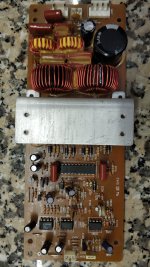
It is a Kenwood SW-505D subwoofer. It sounds very distorted, you have to select near full the volume to make it sound something low like a trapped fly...prf prf prf prf prf prf prf
I'm just an amateur without much knowledge, but I think I put my heart into it. I think, that the failure is in this board... any help will be appreciated, thank you!
The voltages on the HIP4080 are:
P1: 11.63v
P2: 12,14v
P3: 0,34v
P4: 0,011v
P5: (not soldered on board) variable around 0,520v with the volume at 0 and around (oscillating) 4,80v at max
P6: 6,21v
P7: 9,27v
P8: 5,18v
P9: 5,18v
P10: 11,64v
P11: 0,028v
P12: 0,028v
P13: 11,26v
P14: 0,011v
P15: 12,14v
P16: 12,14v
P17: 0,011v
P18: 0,39v
P19: 0,009v
P20: 0,010v
IC3
P1: 9,90v
P2: 6,57v
P3: 6,59v
P4: 0v
P5: 5,814v
P6: 5.814v
P7: 6,051v
P8: 12,13v
IC2
P1: 6,059v
P2: 6,059v
P3: 6,055v
P4: 0v
P5: 6,059v
P6: 6,059v
P7: 6,21v
P8: 12,13v
IC1
P1: 0v
P2: 0v
P3: 0v
P4: 0v
P5: 6,103v
P6: 6,059v
P7: 5,161v
P8: 12,13v
I have desoldered about half of the components of the boards and I can not detect what is happening....
It is a Kenwood SW-505D subwoofer. It sounds very distorted, you have to select near full the volume to make it sound something low like a trapped fly...prf prf prf prf prf prf prf
I'm just an amateur without much knowledge, but I think I put my heart into it. I think, that the failure is in this board... any help will be appreciated, thank you!
The voltages on the HIP4080 are:
P1: 11.63v
P2: 12,14v
P3: 0,34v
P4: 0,011v
P5: (not soldered on board) variable around 0,520v with the volume at 0 and around (oscillating) 4,80v at max
P6: 6,21v
P7: 9,27v
P8: 5,18v
P9: 5,18v
P10: 11,64v
P11: 0,028v
P12: 0,028v
P13: 11,26v
P14: 0,011v
P15: 12,14v
P16: 12,14v
P17: 0,011v
P18: 0,39v
P19: 0,009v
P20: 0,010v
IC3
P1: 9,90v
P2: 6,57v
P3: 6,59v
P4: 0v
P5: 5,814v
P6: 5.814v
P7: 6,051v
P8: 12,13v
IC2
P1: 6,059v
P2: 6,059v
P3: 6,055v
P4: 0v
P5: 6,059v
P6: 6,059v
P7: 6,21v
P8: 12,13v
IC1
P1: 0v
P2: 0v
P3: 0v
P4: 0v
P5: 6,103v
P6: 6,059v
P7: 5,161v
P8: 12,13v
Attachments
I would suspect the output FETs or the 4080 driver chip or a component in the output stage. Sound is getting through but it is not being amplified. High voltage and high current components usually fail first. If would be useful to have an oscilloscope to monitor the gate drive of each FET and the drain of each FET. There should be a square wave on each gate and each drain at a high frequency like 100 Khz or higher. You could check the output FETs for shorts with an ohm meter but it is more likely that one or two of the output FETS are open circuited. The switching circuit is part of a feedback loop and that loop can be broken by a support component like a capacitor or a resistor. It may oscillate at a very low or a very high frequency or not at all depending on which component/s have failed.
I was mistaken about all the drains having a square wave on then since this is an all N-channel output stage and some drains are tied to a supply.
Many thanks James, I changed all the mosfets but no noticeable changes, the older seems OK on the handy tester. At night take readings for each pin on them. Will try to order a HIP4080 to try other driver and see what happens, although if it were possible to rule out that this one doesn't work... it would be great

Thanks all guys for the answers. The -12v issue... it should be on the pin 4 of the CN5 of the board, and should reach the Q204 (DTA124ES) but there is nothing, it should come from the TR310 (DTC114ES) of the power supply mainboard, there is 0,003v base, 4,987v collector and 0,003v emitter.
On the IC303 I have Input 21,42v, Gate 0v, output 12,11v.
On the IC304 I have Input -21,36v, Gate 0v, output -12,10v.
On the IC303 I have Input 21,42v, Gate 0v, output 12,11v.
On the IC304 I have Input -21,36v, Gate 0v, output -12,10v.
The readings on the mosfets, I suppose they are not quite relevant:
Q207:
S: -0,011v
D: 74,0v
G 0,010v
Q208
S: -0,011v
D: -0,011v
G 0,037v
Q209
S: -0,011v
D: -0,006v
G 11,57v
Q210
S: -0,006v
D: 74,3v
G 0,018v
Q207:
S: -0,011v
D: 74,0v
G 0,010v
Q208
S: -0,011v
D: -0,011v
G 0,037v
Q209
S: -0,011v
D: -0,006v
G 11,57v
Q210
S: -0,006v
D: 74,3v
G 0,018v
Thanks James, Between P20 and P17 there are 4,81Mohms, small decreasing in some seconds starts about 5,02 MOhms (black prob on P20, red con P17) reversing 6,35MOhms static.
Your data shows that there is no short to ground on Pin 20. Another possibility is that Pin 20 is open internally and not able to drive Q207. When a transistor fails it can create a short or an open circuit. I am pretty sure that there is an internal diode from Pin 20 to Pin 17 and a similar diode from Pin 20 to Pin 16. If you have a volt meter that checks diodes then you can check to see if those diodes are there. If you can measure these 2 diodes then pin 20 is not open and may be fine. On the other hand, if one or both of these diodes are missing then the 4080 likely has an internal open circuit. I am not sure what kind of drivers are present in the output of the 4080 but I think that they are CMOS or DMOS transistors. DMOS and Bipolar drivers would have diodes but I am not sure about CMOS drivers. The data sheet leaves one guessing about what kind of drivers are present but I would guess DMOS.
Thanks for your follow up James, I desoldered pins 17 to 20 of the HIP4080 to isolate them from the board and verified that I had no continuity between the pin and the board track.
On the diode scale, from pin 20 to 17 (black probe to red) it shows 2,25 on reverse infinite (0L). From P20 to 16, goes about around 1,88 to 1,90 scaling slowly, seems to be a capacitor related involved or similar, on reverse reading is infinite. Maybe I need to remove out the IC to check?
On the diode scale, from pin 20 to 17 (black probe to red) it shows 2,25 on reverse infinite (0L). From P20 to 16, goes about around 1,88 to 1,90 scaling slowly, seems to be a capacitor related involved or similar, on reverse reading is infinite. Maybe I need to remove out the IC to check?
Well, you proved that pin 20 is not open or shorted. If I read the state table in the datasheet correctly then pin 13 and pin 20 should both be high in that state with uv, hen, dis, and vin+ > vin-, as inputs. So, its seems that the internal logic in the chip is faulty. I will double check later when I have more time but it looks like the 4080 logic is faulty.
I checked again and I think that the chip is not following the logic in the data sheet. The input voltages on the logic pins are telling Pin 20 and Pin 13 to be high but only Pin 13 is high. It looks like the 4080 is bad.
Just to be clear, does 4,81Mohms mean 4.8 million ohms or 4.8 milli ohms? I took it as meaning a million ohms.
Just to be clear, does 4,81Mohms mean 4.8 million ohms or 4.8 milli ohms? I took it as meaning a million ohms.
Last edited:
Many thanks both, yes, MOhm is the greatest scale of reading on this tester, million ohms. Will order a pair of this hip4080 just to check. I will let you know when they arrive.
In the other hand, could some one point me to find where is the -12,4v line lost? I don't understand if the -12v is generated at the power supply board or if it comes from the hip8040 board, since there is a power transistor Q203 (KTA1023Y on schema A1275 in place).
On the power supply board appear that the -12,4v goes from the IC304 to the PIN1 of the CN2B and there is -12,4 and also there is a joint that goes to the PIN 1 of CN5, but there isn't, seems to reach Q204 but there are 0v. Also there isn't the 10,2v on the TR306 line, there are around 3,6v... I'm quite lost
Thanks all guys for the answers. The -12v issue... it should be on the pin 4 of the CN5 of the board, and should reach the Q204 (DTA124ES) but there is nothing, it should come from the TR310 (DTC114ES) of the power supply mainboard, there is 0,003v base, 4,987v collector and 0,003v emitter.
On the IC303 I have Input 21,42v, Gate 0v, output 12,11v.
On the IC304 I have Input -21,36v, Gate 0v, output -12,10v.
Attachments
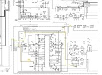
Take a look at the board view schematic at the top of the manual. All chips starting with 2 are on the amplifier/output board. All chips starting with 3 are on the main board. CN5 you have highlighted on your picture is a connector, follow it up to the output board. That is showing, more than likely, a ribbon cable. A lot of the chips want +-12V. Also looks like 2 of the output MOSFET's should be getting -12V, the other two +12V.
See the attached for my partial trace of -12V routes.


See the attached for my partial trace of -12V routes.
- Home
- Amplifiers
- Class D
- Please, help to fix my Class D Kenwood Subwoofer