I'm only going on what I can see at Michael's web site. The picture shows D8 on the board. Michael says remove, I was just making sure you didn't bridge it..You have your polarity right? it worked with your power supply before mods?
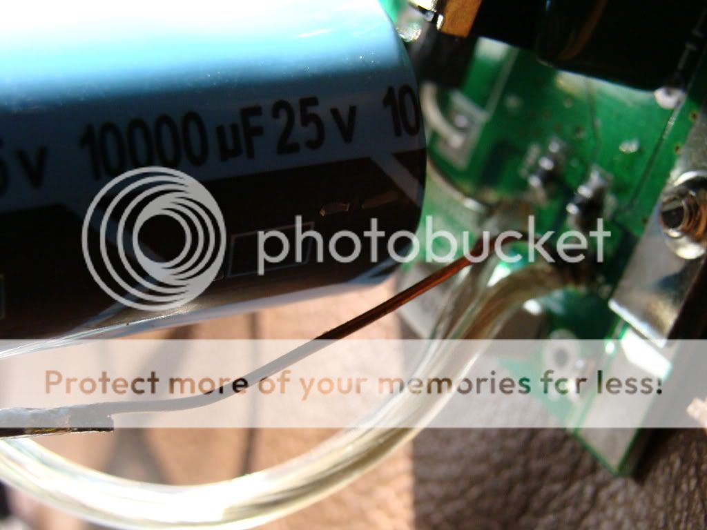
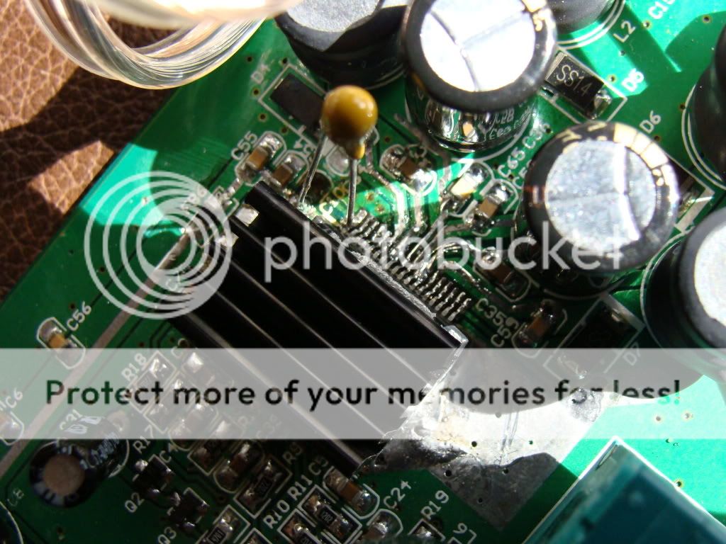
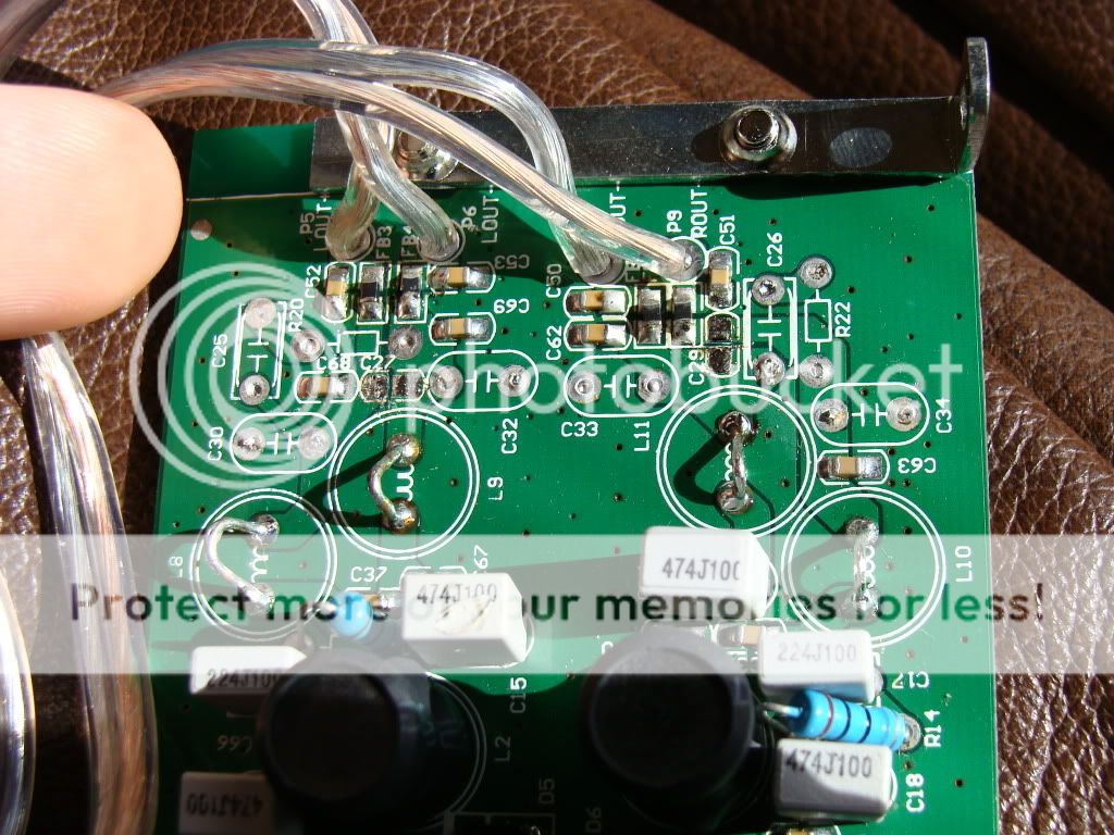
Yes I left all of the diodes alone. It also worked before with this power supply. Here are some pics.
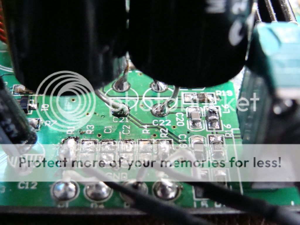
I must thank you for your tremendous help. There was a slag of metal from the solder that was barely touching the power connector plug in an area that I could not see easily. I have power now, but the left channel is DC'ing. Only have sound from the right channel. Any ideas?
Check for shorts around the R3 & R4 area. Check you have continuity between input and your new solens..
I can't see any shorts at R3 or R4. The center pin of the left channel gets continuity at R1 and the top pins of R3 and C1. Right channel gets continuity at R2 and the top pins of R4 and C2. This is with the power switch on with no power running through the unit.
Last thing to try I'm afraid.
Pot at max, no power, test resistance from R1 to leg of left channel Solen. Also you could test resistance from each side of C37 to + & - of left speaker.
Pot at max, no power, test resistance from R1 to leg of left channel Solen. Also you could test resistance from each side of C37 to + & - of left speaker.
Alright.
One probe on R1
Other probe on
Top of left: 84K
Bottom of Left: 2.6K
Top of Right: 129.5K
Bottom of Right: 43.5K
One probe on R2
Other probe on
Top of Left: 43.6
Bottom of Left: 43.6
Top of Right: 133
Bottom of Right: 5.1
I assume you mean C9 as that is the 470micro farad cap for the left channel.
From the pin farthest from the outputs: 19.6Meg or infinite.
From the pin closest to the outputs: 16.3K
Any ideas? Those numbers for the input caps seem a little strange.
I put one probe on the ground input for the board from the power connector
The other probe on
Top of left solen: 19.9K
Bottom of left solen: 19.9K
Top of Right solen: 109.3K
Bottom of Right solen: 23.6K
The other probe on
Top of left solen: 19.9K
Bottom of left solen: 19.9K
Top of Right solen: 109.3K
Bottom of Right solen: 23.6K
I think the left solen is blown. It reads 87 ohms resistance across the leads. Isn't it supposed to steadily increase? The right Solen increases up to 133K. I knicked that one with the soldering iron, I wonder if that messed it up. Also the left gets continuity on both sides from the input. The right only get momentary continuity on the top and full continuity on the bottom.
It looks like the problem is with the Solens. I would try re-soldering them. It sounds like you may have to replace them. Try different caps or the originals to see if the problem goes away..
Alright I will do that and get back with you with the results. I can't thank you enough for your assistance.
I went and resoldered the caps to the board. I am having increasing difficulty as there is some "junk" on the pads. Now there doesn't seem to be dc on the left channel there is just no sound from the left channel. When I place my finger on the top of the cap I get a humming noise but there is no sound otherwise.
Is that "junk" you speak of solder flux residue? Some isopropyl (rubbing) alcohol should be able to take care of that.
- Status
- Not open for further replies.
- Home
- Amplifiers
- Class D
- Please help, I attempted to mod a TAmp and the fuse blew.