Hi!
You can use 2 damper diodes in a full wave rectification scheme with a transformer with center tap. As an example see here:
VinylSavor: Single Ended Amplifier Concept, Part 7
4 tubes can be wired as a full wave bridge and doesn't need a center tap. here is a wiring example with 6AX4:
VinylSavor: Tube of the Month: The 6AX4
The bridge delivers twice the DC voltage compared to the 2 diode rectification.
Thomas
While the forward drop in damper diodes is relatively small, it is still quite large in comparison to SS. Therefore, build the 4 diode bridge out of 2X "noiseless", high PIV, Schottky diodes on the "cold" side and a pair of damper diodes on the "hot" side. The sonic signature of the hybrid bridge is totally dominated by the vacuum diodes.
Added benefits of the hybrid bridge are reduced heater current requirements and avoidance of heater to cathode potential limit trouble.
Added benefits of the hybrid bridge are reduced heater current requirements and avoidance of heater to cathode potential limit trouble.
Hi Eli,
I do exactly that, when space is restricted to have 4 tube diodes. As in this latest 6CB5A build:
VinylSavor: Making of a SE 6CB5A amplifier: circuit
But ultimately I prefer the all tube bridge for it's symmetrical behaviour
Thomas
I do exactly that, when space is restricted to have 4 tube diodes. As in this latest 6CB5A build:
VinylSavor: Making of a SE 6CB5A amplifier: circuit
But ultimately I prefer the all tube bridge for it's symmetrical behaviour
Thomas
Hi!
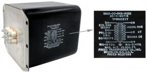
Nice power transformer. If I interpret the spec correctly, it is 1400V across the entire secondary (700-0-700V). In that case, you can get about 800-900V with a 2 diode full wave rectifier. To obtain 1300VDC you will have to use a bridge. Use a choke input filter with a small cap before the first choke to adjust the voltage you need.
If you want to use 4 tubes, you will have to use at least 3 separate heater windings to keep heater-cathode voltages within limits. Or use Elis suggestion and connect the heaters of the tubes to B+. Watch the peak inverse voltage on the semiconductor diodes in that case! You will need to use several in series. You can use PSUD simulation to determine the peak inverse voltage and the size of the first cap to get your results
Thomas
Yes. You are right. 1400VDC from pin 4 and 6.
Thank you.
My amp has ONE filament transformer to run all 4 6CJ3 tubes.
Thank you.
My amp has ONE filament transformer to run all 4 6CJ3 tubes.
My amp has ONE filament transformer to run all 4 6CJ3 tubes.
Thomas has already explained that you can't run all 4 heaters of a vacuum bridge off the same filament winding. So, you must use a hybrid bridge. The easiest way is to use a series connected pair of UF4007s in each of the bridge's "cold" side legs. As UFnnnn diodes produce a tiny amount of switching noise, snub each SS diode pair with a HIGH WVDC 0.01 μF. capacitor.
Last edited:
In my amp, the filament of each 6CJ3 is NOT connected to the plate or cathode.
But in Thomas' schematic, the filament is connected to plate and cathode.
But in Thomas' schematic, the filament is connected to plate and cathode.
Hi!
It depends on the voltages which can appear between heater and cathode. Check the datasheet, it states the allowable limits which should be ensured. For lower voltage applications all heaters of a bridge can be referenced to ground and fed from a single heater winding
Thomas
It depends on the voltages which can appear between heater and cathode. Check the datasheet, it states the allowable limits which should be ensured. For lower voltage applications all heaters of a bridge can be referenced to ground and fed from a single heater winding
Thomas
For my application, is the set up ok?
My amp has 30mV (120Hz) hum on R and 13mV (60Hz) hum on L channel.
Any suggestion on how to fix this ?
My amp has 30mV (120Hz) hum on R and 13mV (60Hz) hum on L channel.
Any suggestion on how to fix this ?
Last edited:
Yes, the hums are measured at speaker terminal with 8 ohm resistor in place.
It is SE amp with Eimac 250TL power tube and 75TL as driver tube.
It has single PS for both channels and also Power and driver stages.
cap coupling between driver and power tube
It is SE amp with Eimac 250TL power tube and 75TL as driver tube.
It has single PS for both channels and also Power and driver stages.
cap coupling between driver and power tube
Hi!
That's a lot of hum at the speaker terminals. Can you post a schematic?
Are you using TV dampers already? If heater cathode voltages are exceeded in a circuit, the tube doesn't necessarily fail immediately. It can work for some time and then develop a heater-cathode short. Make sure you are within the limits!
Thomas
I don't understand this question.Are you using TV dampers already?
I do not have a schematic.
I attached the 6CJ3 datasheet.
Heater positive to cathode at 100V ?
Heater negative to cathode at 900V ?
Are you referring to:If heater cathode voltages are exceeded in a circuit, the tube doesn't necessarily fail immediately. It can work for some time and then develop a heater-cathode short. Make sure you are within the limits!
Heater positive to cathode at 100V ?
Heater negative to cathode at 900V ?
Attachments
Last edited:
I don't know which pins are heater + and -
I measured between heater pin 4 and cathode (pin 9)
I also measured heater pin 5 and cathode. Both have 170VDC
I measured between heater pin 4 and cathode (pin 9)
I also measured heater pin 5 and cathode. Both have 170VDC
Hi!
The heater pins don't have apolarity since they are usually supplied by AC. Both values need to be respected. Also both DC component and peak value of the voltage difference needs to stay within limits. It would be easier if you post a sketch of the schematic to check if you are ok.
Thomas
The heater pins don't have apolarity since they are usually supplied by AC. Both values need to be respected. Also both DC component and peak value of the voltage difference needs to stay within limits. It would be easier if you post a sketch of the schematic to check if you are ok.
Thomas
- Status
- Not open for further replies.
- Home
- Amplifiers
- Tubes / Valves
- Please Help: 6CJ3 Damper Diode Tube as Rectifier Question