If the schematic earlier is the latest version, then you may have missed out the compensation for the error correction?
Where do you guys get your KSA3503 etc.
If you are not worried about the Hfe grade for the A3503/C1381. Try RS, they have added quite a few KSA/KSC transistors recently.
Paul
Do you mean KSC3503 in my schematic? I got the KSC3503 from Digikey if that's what you are looking for http://www.digikey.com/scripts/DkSe...uq=635573191974409900&CSRT=748577047426600569Where do you guys get your KSA3503 etc.
In fact, all the pasts are from Digikey.
Last edited:
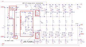
I have the error correction in the latest revision in post #8!!! The error correction is there and is a straight copy from Mr. Cordell without the capacitor compensation. I figure I'll never use it, just put it in if one day I'll try the MOSFET.If the schematic earlier is the latest version, then you may have missed out the compensation for the error correction?
I have the error correction in the latest revision in post #8!!! The error correction is there and is a straight copy from Mr. Cordell without the capacitor compensation. I figure I'll never use it, just put it in if one day I'll try the MOSFET.
You may as well layout for the compensation. You can't use the HEC OPS without it. Seems a waste to put all that circuitry there are not have it complete.
An HEC MOSFET OPS can sound very nice. Worth serious consideration in the future. You'd be surprised how good inexpensive components can sound.
You may as well layout for the compensation. You can't use the HEC OPS without it. Seems a waste to put all that circuitry there are not have it complete.
An HEC MOSFET OPS can sound very nice. Worth serious consideration in the future. You'd be surprised how good inexpensive components can sound.
If you are familiar with the error correction circuit, can you help me take a quick look at the circuit to confirm I am right? That was from Cordell's paper back in 1981!!! Yes, I should put the compensation in.
Thanks
If you are familiar with the error correction circuit, can you help me take a quick look at the circuit to confirm I am right? That was from Cordell's paper back in 1981!!! Yes, I should put the compensation in.
Thanks
Your circuit in post 8 looks ok to me. However, would need to simulate the stability of the HEC with the diode and speed up capacitor to see the affect. In my experience with HEC a speed up capacitor is not necessary just run a high bias current for the drivers.
Here is an amplifier I designed and prototyped with HEC. Could be a useful reference...?
http://www.diyaudio.com/forums/solid-state/261304-cfa-amp-cmcl-hec-output-stage-3.html#post4082963
This is some useful information regarding setting up the HEC. Follow this method and you end up with a rock solid HEC. 🙂 Thank you CBS240.
http://www.diyaudio.com/forums/solid-state/246700-random-amp-questions.html#post3795772
Hope this helps.
Paul
I just realize it's a big mistake to put the diode in. The reason is the emitter resistance will be very low ( 10 ohm). This will low the input resistance of the EF stage as even the beta is 100, the input impedance at the base is 100 X 10 =1K!!! That is not acceptable. We try so hard to put 3EF to raise the input impedance of the OPS, this destroy everything.
The cap across the two emitters lower the impedance also, that has to go too!!!
So much for the "bright idea"!!! I am going to remove the diodes and raise the emitter resistance tomorrow and post the schematic.
The cap across the two emitters lower the impedance also, that has to go too!!!
So much for the "bright idea"!!! I am going to remove the diodes and raise the emitter resistance tomorrow and post the schematic.
So you use simulation to find the bias current of the power transistors?
Do you mean the emitter resistor in between Q26 and Q27 in my schematic? Even if I don't use a 1N4007 diode to take up 0.7V I use 27ohm resistor to draw 50mA of tail current from Q26 and Q27. If my guess is right that you use 100ohm between the two emitters? That would be 14mA or so of tail current only!!!
Do you mean you put a 1uF cap across the 100ohm resistor between the two emitters? Like I put a 10uF//01.uF between the two emitters of Q26 and Q27?
I have not even start to think about simulation, I figure this only affect the value of the components. The most important thing for me is to get the pcb right so I am covered for all possibilities. Do yo use LTspice? that's what I have. Just need to find the model of all the transistors.
Thanks
The 2 groups of ON semi models I have (Cordell's and the OEM's) bottom
out -THD wise .... at 70mA bias and increase <40 and >120ma.
Also , a strange thing happens with a CFA , the optimum bias range shifts lower
and wider.
I use LTspice , BTW. Oh , here are the models....
OS
Attachments
8turns around a bobbin the same size as an AA battery, gives approx 7uH to 8uH....................
BTW, I forgot where your posts on winding the output inductor. I remember you said you wound on an AA battery, how many turns and what gauge insulated copper wire? So many things to think about. I have been searching parts day and night, work harder than a real job!!! Still have the front end IPS and VAS board, power supply board ( maybe) and definitely output relays to protect the speakers. I really need a vacation from my hobby!!!
Thanks
You can use any diameter of enameled copper wire.
0.6mm gives a high DCR, 3mm gives a low DCR.
Choose what suits your speakers and your other resistances in the output circuit.
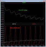
voltage sag in the PSU and voltage drops through the amplifier when delivering high peak currents add up to significant voltage loss......................I think you guys are right about 40V is a little too low for the rail. I decided to go to 50V to give some headroom for the ripple voltage. ..............
Expect a 35+35Vac transformer giving ~+-50Vdc to yield a maximum output of at least 40Vpk into 8r0 test load (>100W into 8r0). A very good PSU and very good amp can give upto 42Vpk into 8r0
Your 4pair output stage should give at least 40Vpk into 4r0 and probably >38Vpk into 2r0.
note the "losses" including allowances for transformer and wiring and ripple and output stage Vce and pre-driver+driver Vbe, add up to ~ 8V for 8ohms, 10V for 4ohms and 12V for 2ohms.
Much worse than this indicates a compromise taken "too far".
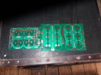
That's a nice looking guts. Where is your toroidal transformer? Is that an inductor on the pcb in the middle that looks like a small transformer?
What is your power filter? Is it CLC? What value are you using?
The 1Kva is under the protection PCB. The small PCB trafo is a 25VA 14V unit.
Powers soft-start , AC on relays. DC/overload/temperature faults will shut
down the speakers. Rail sensor will switch off the main AC.
Most of these fault conditions (and relay timings) can actually be changed in javascript on the little microprocessor.
No CRC , just dual 35A bridges driving 3pair 6800uf per channel
(12 caps -82Kuf total / 73-0-73V rails).
OS
I just finished updating the schematic.
1) Adding C10 as per Cordell's circuit in the error correction circuit.
2) Adding two optional lead lag network on the base of Q26 and Q27 as optional compensation for stability in GNFB. They are not going to stuffed unless necessary.
3) Adding the 5th output stage to increase quiescent current.
Major moving of stuffs on the schematic, I won't be surprised there are errors again. Let me know anything else I should include in this universal OPT board.
Thanks
Attachments
Last edited:
The 1Kva is under the protection PCB. The small PCB trafo is a 25VA 14V unit.
Powers soft-start , AC on relays. DC/overload/temperature faults will shut
down the speakers. Rail sensor will switch off the main AC.
Most of these fault conditions (and relay timings) can actually be changed in javascript on the little microprocessor.
No CRC , just dual 35A bridges driving 3pair 6800uf per channel
(12 caps -82Kuf total / 73-0-73V rails).
OS
I still yet to design the speaker cut out relay to protect the speaker. The amp can catch on fire for all I care. If I burn the speakers, that will be really bad!!!
Do you have recommendation on the speaker relay?
So you use separate bridge rectifiers for each channel and 20,000uF for each rail per channel.
Thanks
Hi Alan,
A few comments...
Would take your optional RC networks to the rail instead of GND.
RC networks across R34 and R35. Must have for compensation of HEC.
Gate to Drain zobels (RC networks) for MOSFET option unless you are going to solder directly to the MOSFET pins. Which IMHO is better anyway. 😉
As for protection relays. Solid state seem like a good idea.
Paul
Edit: Some reading. Solid state relays.
http://hifisonix.com/wordpress/wp-content/uploads/2013/01/Simple_solid_state_relay_Updated.pdf
Last edited:
Hi Alan,
A few comments...
Would take your optional RC networks to the rail instead of GND.
RC networks across R34 and R35. Must have for compensation of HEC.
Ha ha, my eyes did a trick on me, I just did not see that. I'll add that. Thanks
Is that to prevent local parasitic oscillation of MOSFET. So you want to have low impedance from gate to drain at high frequency? What is the usual values? I am going to solder directly onto the MOSFET when the time comes. I have a hell of a problem trying to keep the pcb width down!!!Gate to Drain zobels (RC networks) for MOSFET option unless you are going to solder directly to the MOSFET pins. Which IMHO is better anyway. 😉
As for protection relays. Solid state seem like a good idea.
Paul
You put SS relay between the output and the speaker? Is that bad?
Thanks for you help. I still need to read your schematic, my head is spinning choosing parts!!!
Ha ha, my eyes did a trick on me, I just did not see that. I'll add that. Thanks
No problem.
Is that to prevent local parasitic oscillation of MOSFET. So you want to have low impedance from gate to drain at high frequency? What is the usual values? I am going to solder directly onto the MOSFET when the time comes. I have a hell of a problem trying to keep the pcb width down!!!
Yes, it provides some local feedback to damp oscillations. Typical values are in the order of 10-100pF and around 22-220R. Some people like to use far more extreme values...
The trade off for more local feedback is a reduction in global stabiliy margins (PM/GM).
You put SS relay between the output and the speaker? Is that bad?
Thanks for you help. I still need to read your schematic, my head is spinning choosing parts!!!
Not really. See the edit above. You could always put SS relays in the power rails instead?
It's a steep learning curve isn't it? And it does make your head spin. Sometimes I have to walk away from a design for couple of days to clear my head. 😉 It's very rewarding when you sit down and listen to you creation when its finished.
Don't spend too much time on that amplifier. It was very complicated and better performance has since been obtained with a more simple design.
It was really just to illustrate what I was using for the HEC. It was a good learning exercise...
Paul
Last edited:
I still yet to design the speaker cut out relay to protect the speaker. The amp can catch on fire for all I care. If I burn the speakers, that will be really bad!!!
Do you have recommendation on the speaker relay?
So you use separate bridge rectifiers for each channel and 20,000uF for each rail per channel.
Thanks
yep - 3 caps parallel per rail ... actually cheaper ,easier to source , lower ESR.
Bad thing is having to make PCB's for multiple parallel caps. (below).
Jwilhelm (maker of the control board) , actually has some 50A mosfet relay
replacements . Most mechanical relays are both slow and can "weld" on a
severe fault.
A solid state relay is just 2 low RDSon (<50u ohm) mosfets ...
triggered by an opto-isolator.
Your latest EF3 is better , 100K Z on the input. 47R to decouple the driver/pre is
a little high. They (the drivers) might need a bit of current. 5-10R here is better.
(below 2) shows driver collector load at 3R/ high power. A 47R here would drop
too much voltage (>5V) ... 4.7R just .5V.
PS - MJL/NJW output devices have a 54ma base current (each) for <3800ma Ic
at 70V = current gain of <70.
OS
Attachments
Last edited:
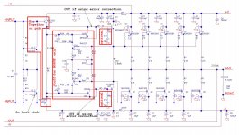
OK, latest revision
1) Add the missing lead lag network from Cordell R36-C6 and R37-C7.
2) Add RT2 250ohm trim pot on the pre-driver output to the error correction circuit. This is to fine trim the amplitude. The output of the pre-driver is always going to be slightly larger than the final output because the gain of the emitter follower is only about 0.95 to 0.97. Might even try 100ohm trim pot as the mismatch is so small.
3) Changing the resistor between the rail voltages of the power transistor to the pre-drivers from 47 to 22 ohm to reduce voltage drop.
Attachments
Last edited:
2) Add RT2 250ohm...
Wouldn't do this myself. Brings you no benefit IMHO.
- Status
- Not open for further replies.
- Home
- Amplifiers
- Solid State
- Please comment on my OPS design