I'm designing my first power supply for a class A/B amp. Searching for filter caps, I found they are often described by the manufacturer as "audio grade", "computer grade", "general purpose" or other descriptions. For a given capacitance and voltage value, the electrolytics described as "audio grade" were among the least expensive, and often the ESR and leak were not listed in the data sheet.😕 Capacitors with the lowest ESR and leak current (and highest price) are usually described as "general purpose", "computer grade", or as being for SMPS. Another thing I found is that all electrolytics described as "audio grade" were only available with radial or snap-in terminals. However, I know that many DIY builders and high-end companies use screw terminal in their PS filtering caps. I would prefer screw terminals, as I'll be point-to-point wiring this PS.
So, to finally get to my questions:
Any advice from more experienced builders is greatly appreciated.
So, to finally get to my questions:
- What, exactly, does a manufacturer mean when they describe their caps as "audio grade"? Nichion's data sheet describes this as "Realization of a harmonious balance of sound quality, made possible by the development of new electrolyte."😕😕😕 And why would they bother with the hype for their least expensive caps?
- How important are the values of ESR, leak current, and ripple current in PS filtering caps?
- What are all these high-end, high power amps with screw terminal PS filtering caps using?
- Just where is the point of diminishing returns for filter cap quality?
Any advice from more experienced builders is greatly appreciated.
Attachments
Last edited:
The design looks like overkill so the capacitors will be not be stressed. Even 80V pcb mount types should do. SMPS rated devices usually have low ESL and ESR. 105C rated devices last longer.
Use the equivalent circuit of the components in the simulation to simulate what effect of ESL leakage and ESR are. Google and wikipedia will help explain both transformer and capacitor equivalent circuits.
Audio is not a demanding application so that is why audio capacitors should be cheaper. Forget any marketing diatribe, that is what happens when anything enters the consumer market
There are radical difference in the expected life of caps. Depends on whether they use the rubber sealant, or the expensive stuff. I buy the one with the 8000 hour life rating at 105 deg C if I can get it, 2000 hr if I can't. A lot of 1000 hour caps are still stocked for repair people whose customers don't care. Usually ESR doesn't matter in these life ratings, but 10000 uf comes in a much cheaper "tall' version with *****y ESR. Replacing some 10000 uf @ 100V recently, I bought twice as many 4700 uf caps at 5/4 the ESR and 1/3 the price each. Then I doubled them up on a little CB I made with lexan, 18 ga wire, and steel angle brackets. Glued the caps down with silicon seal, but wall board adhesive will work as well. Weren't a lot of choices in 10000 uf caps, looking for in stock items only. These were radial, soldered the wire to the leads through the new CB. The stock spacing (10 mm) and the old "4 peg" spacing, did not match.
The only thing I've noticed about "audio" caps is that mcmelectronics charges about 4 times as much for them as the series I find in AB motor drives- the ones that run 8 years in an industrial oven motor compartment.
The only thing I've noticed about "audio" caps is that mcmelectronics charges about 4 times as much for them as the series I find in AB motor drives- the ones that run 8 years in an industrial oven motor compartment.
Last edited:
The LED won't last long 😉
By far the biggest contributer to noise/distortion/hum etc etc etc is your physical layout of all the tracks on the PCB for the main amplifier and what connects where on those tracks.
PSU's are important but just throwing lots of capacitance isn't the answer IMO. A good amp rejects rubbish on the rails anyway.
Also the more capacitance on the rails and the shorter the time the bridge conducts for... but the same energy as lower capacitance rails still has to be put back for a given load. That means the peak currents are correspondingly higher, copper losses become significant and the transformer may well technically be pushed beyond its ratings.
Thanks everyone! I was worried no one would respond to me post. Then all of a sudden . . .
Transformer is rated at 300VA, and I'll be using two. It's a dual-mono design. I included the data sheet, but I don't know how to interpret all those numbers. Do you think they might be stressed? Of course, it's kind of late now.
Included is the data sheet for the filter cap I decided on. It's new at Mouser.
Thanks again for the advice!
Yes, when unsure of what I'm doing, I prefer to overbuild than underbuild. I may, at some point in the future increase transformer voltage. I'm using these 40V transformers because I already have them. The board is designed for 64V rails. I'm really insisting on screw terminals because I'm not going to make a board for this.The design looks like overkill Even 80V pcb mount types should do.
I chose one with 8400 hour life rating, but at 85 C. Like Metalsculptor said, I won't be stressing these caps.I buy the one with the 8000 hour life rating at 105 deg C if I can get it, 2000 hr if I can't.
What is wrong with my LED? I admit, I didn't give it much thought. Can I just increase the value of the resistor in series with it, or should I get a beefy-er LED? What do you think of this LED? 4302F1-12V Chicago Miniature Standard LED - Through HoleThe LED won't last long 😉
Also the more capacitance on the rails and the shorter the time the bridge conducts for... but the same energy as lower capacitance rails still has to be put back for a given load. That means the peak currents are correspondingly higher, copper losses become significant and the transformer may well technically be pushed beyond its ratings.
Transformer is rated at 300VA, and I'll be using two. It's a dual-mono design. I included the data sheet, but I don't know how to interpret all those numbers. Do you think they might be stressed? Of course, it's kind of late now.
Included is the data sheet for the filter cap I decided on. It's new at Mouser.
Thanks again for the advice!
Attachments
What is wrong with my LED? I admit, I didn't give it much thought. Can I just increase the value of the resistor in series with it, or should I get a beefy-er LED?
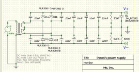
...it is because your schematic in post#1 has a 'typo'. It shows the junction of the LED and its R tied to ground.
Use any LED, calculate R for 2-5 mA. It will last forever.
On a side note, the 500 ohm discharge Rs you have are somewhat counter productive (120 mA, 7W at 60V). I usually do not use them, but consider 10k minimum if you must.
Last edited:
OOPS!
I might have built it like that if you hadn't pointed it out to me.
Yeah, 500R is way too low. I'll up the bleeders to ~2kR.
Thanks for the help!
...it is because your schematic in post#1 has a 'typo'. It shows the junction of the LED and its R tied to ground.
Use any LED, calculate R for 2-5 mA. It will last forever.
On a side note, the 500 ohm discharge Rs you have are somewhat counter productive (120 mA, 7W at 60V). I usually do not use them, but consider 10k minimum if you must.
I might have built it like that if you hadn't pointed it out to me.
Yeah, 500R is way too low. I'll up the bleeders to ~2kR.
Thanks for the help!
An intermediate value between 200nF and 10,000uFs will be helpful in suppressing LC resonances between the caps---I don't have the link handy but there's a great thread in this forum (or maybe solid state) with quite a bit of data on the issues. A good rule of thumb for avoiding the problem is two order of magnitude steps; it varies from design to design and board to board but I often end up with 100nF 0603 X7R || 4.7uF 1206 X7R || 220uF 5mm aluminum || 22,000uF 25mm aluminum as a starting point. At higher voltages you'll need a 'lytic for the low uF range and a larger package on the MLCCs.
If you look at the datasheets you'll see the KWs have slightly higher ripple current ratings than VRs, implying a little bit lower ESR. Otherwise they're identical, though it's possible the KWs might have somewhat higher self resonant frequencies---I've not seen measurements but I'd frankly be surprised if there's much difference beyond marketing induced placebo effects. If your amp's PSRR is low enough the ESR, ESL, and self resonant frequency of the caps is a concern you either need a better amp design, regulation, or caps which are speced in more detail (TDK's online app is great for MLCCs, Nichicon LF and HE are good staring points for higher performance cans). Generally it's easiest just to regulate the amplifier's control loop---with care one can get discrete PSRRs approaching 100dB at certain frequencies but an op amp for control running off some LM7xL15s is pretty turnkey and offers 120+dB PSRR over the entire audio band (some will say this is overkill but every time I run the math for my amps it's about what I end up with).Nichion's data sheet describes this as "Realization of a harmonious balance of sound quality, made possible by the development of new electrolyte."😕😕😕
Last edited:
Thanks twest820. I understand your first suggestion, and I think I'll add a pair of 5000uF electrolytics.
I didn't follow the second part. I'm relatively new to this with no formal training in electronics. I don't know what you mean by "KWs" and "VRs". I also don't know what the amplifier's PSRR (Power Supply Ripple Resistance?) is, or how to figure out how good it is. I'm relying on the reputation of the designer. It's the DX Blame MKIII by Carlos Mergulhao.
HornTube, I assume these are the "long life" caps. How are these better than the myriad of other capacitors available?
Generally capacitors rated for 1000 or 2000 hours working at the other rated values in the datasheet, for example low ESR capacitors anticipated to be used in a switching power circuit rated for 1000 hours will last over 15 years easily when just filtering 120Hz rectified mains in a linear PSU - provided they are not defective /Chinese generics with an unstable electrolyte that breaks down prematurely.
85C vs 105C rating... sure, pick the higher rating if the caps run on the warm side, or that and higher lifetime ratings if you just want the peace of mind that comes from putting more money into parts... certainly a passively cooled amp can have an elevated internal temperature, but there's a big difference in lifetime ratings for caps depending on their anticipated use, and then when you factor that people are using an order of magnitude more capacitance than expected per the currents involved, lifetime ratings really aren't a factor in audio outside of switching power supply or class D audio circuits, UNLESS it's a defective or very poor quality, junk brand capacitor.
Where ESR makes the most difference in PSU/amp pairings of this type is the last pair of caps adjacent the amp's output stage _on_the_amp_board_, whether that output stage be discrete transistors or an integrated chipamp IC. On the PSU board... you've got the traces, connectors, wires, making capacitor ESR a fraction of total series resistance
Pretty close; PSRR is power supply rejection ratio. You can probably find measurements for the amp design in question. There's plenty of design discussion around PSRR that you'll find on a search.I understand your first suggestion, and I think I'll add a pair of 5000uF electrolytics. [...] I'm relatively new to this with no formal training in electronics. I don't know what you mean by "KWs" and "VRs". I also don't know what the amplifier's PSRR (Power Supply Ripple Resistance?) is, or how to figure out how good it is.
You can find the datasheets and classification of Nichicon's capacitor series on their website. KW is the Muse line, VR is the standard parts. I assume 5000uF is a typo and you meant 47uF.
Depends on parts selection and layout. A decent pour on the planes in the 2-10mOhm range for one ounce copper. That's comparable to MLCCs but below the 30-50mOhm of most large 'lytics. And well below the 1-3 ohms typical of smaller electrolytics. If one's doing star ground on a larger board with say, 100 mil traces, yeah then you can the trace impedance up above the reservoir caps. It'll still be below the midsize caps unless you spec some pretty high performance parts---usually cheaper and more effective just to change the design around to improve the PSRR.On the PSU board... you've got the traces, connectors, wires, making capacitor ESR a fraction of total series resistance
Last edited:
I also don't know what the amplifier's PSRR (Power Supply Ripple Resistance?) is,
Power supply rejection Ratio.
Its how well the amplifier rejects any noise on the power rails.
Class AB is quite forgiving with power supplies or so I have found.
Once you get into class D its a whole new ballgame.
I havent had any problems just using 1 pair of electrolytics in class AB.
your 40+40Vac transformer should give <+-63Vdc as a PSU with very light load on it. My 230:40+40Vac transformer gives +-58.5Vdc when mains is at 240Vac and total quiescent current is set to ~200mA.
For this first build I suggest you buy some cheap (but good) 63V caps to make up at least 10mF per rail per channel. i.e. >=40mF for stereo.
For an extension of the very low bass consider 20mF/rail/ch for 8ohm speaker and double this to 40mF/rail/ch for 4ohm speaker.
But before you spend that money try buying some higher quality smoothing caps and compare the SQ to what came with the cheap caps. Is there any difference? That answer will guide your next purchase.
Last edited:
Not much margin. If you look at IEEE statistical data on mains voltage variations the nominal +/-10% is routinely exceeded; +15, -30% is fairly common and there's data out to +25%. That means if the mains run high 63V caps may blow depending on the excess voltage duration and how close the caps' actual breakdown is to rated voltage. Working lifetime also tends to degrade as DC bias approaches the voltage rating; on a 40V trafo I'd be using 80 or 100V caps. However, that's a fair bit of swing. Depends on one's listening arrangement and speaker efficiencies but for many purposes a 15 or 20V trafo's sufficient---of the two designs I've been focusing on lately one uses a 6V trafo and the other a single 5V supply.
(While we're on the topic, anyone wants Antek AN-1220 trafos, PM me; I've literally got a stack of them from an aborted quad amp project that I'm not using.)
(While we're on the topic, anyone wants Antek AN-1220 trafos, PM me; I've literally got a stack of them from an aborted quad amp project that I'm not using.)
HornTube, I assume these are the "long life" caps. How are these better than the myriad of other capacitors available?
I call the Epcos caps the "Axis Powers High-Tech Weapon"😉
It is an alliance between Siemens & Matsushita. They are extremely reliable. Failure is one in a million, maybe. Never experienced one. ESR is very low and they do sound very very good. Punchy, bold, smooth and detailed sound. Suits tube & semicons. Life expectancy is outrageously good - in real life.
The OP and, presumably, most folks reading this thread are not in the UK. You also seem to be confusing the spec on the allowable voltage range in normal operation with under and overvoltage events. The majority of deviations outside the nominal +/-10% range (+10%/-6% in the UK) are voltage dips/sags or undervoltages and therefore won't stress caps. Voltage swells/surges are less common and don't usually last long enough to boil out caps either but more persistent overvoltages do occur and are worth considering in supply design. One's obviously not going to stop everything---for example, I rely on the power company's station arresters to handle gross faults such as 35kV lines shorting to 15kV lines and producing a 2.3x overvoltage---but the incremental costs of avoiding pushing caps to their limits in normal operation are usually trivial. As an example, if one wants to use 63V caps a 32 or 35V trafo is probably the same price as a 40V one since the voltages are close enough they'll likely fall into the same VA rating.The UK tolerance range for mains voltage is 216Vac to 254Vac.
Than you, everyone for all the advice. The caps have already been purchased. They are big 63V, 10,000uF Kemet Aluminum electrolytic 36mm X 97mm.
twest 820: 5000uF was not a typo, but was chosen per your suggestion to add something between 200nF and 10000uF. I've not purchased those yet. I'll see how the supply is working before buying any additional stuff.
Thanks again, everyone.
twest 820: 5000uF was not a typo, but was chosen per your suggestion to add something between 200nF and 10000uF. I've not purchased those yet. I'll see how the supply is working before buying any additional stuff.
Thanks again, everyone.
What I suggested was looking at the motivations behind the default design practice of choosing values roughly two orders of magnitude apart. Unless there's confusion over linear versus logarithmic spacing I'm not seeing a connection between that and the choice of 5000uF.
- Status
- Not open for further replies.
- Home
- Amplifiers
- Power Supplies
- Please . . . advice on filter caps