I'm trying to get a handle on the exact purpose of the plate inductors (usually ~2.2uH) in McIntosh amps.
It seems like these might help isolate the output tubes from output transformer capacitance at high frequencies without causing the resistive losses that a resistor would (like you would see used on the output of an op-amp).
I've recently experienced instability due to the capacitive loading the output transformer itself imposes in a high-feedback SE experimental amp. Putting a few ferrite beads between the feedback circuit and the output transformer cured the problem very well.
I have a Unity-Coupled amp of my own design that has no feedback around the output transformer. I have noticed fleeting signs of instability at times (low level, short duration oscillations on certain waveforms).
I'm going to try adding ferrite beads and was wondering if I should just add in series with the anode like the McIntosh amps, or maybe one to the anode and the cathode? Or maybe it doesn't matter because it is all in series? I'm just having trouble visualizing the best way to do this and what the consequences of doing it one way over the other might be.
If the tube tend to oscillate at high -really high, at MHz region- frequencies, the low value plate choke is effectual.
I'm not convinced in this case the main problem is the high frequency oscillating, rather than the circuit arrangement and parts itself (cross coupling, OPT, choke parameters etc.),
I'm not convinced in this case the main problem is the high frequency oscillating, rather than the circuit arrangement and parts itself (cross coupling, OPT, choke parameters etc.),
Well, I'm going from memory right but I've got the amp back in the workshop and I have better equipment for provoking these issues than I used to have when I built this amp.
My recollection was just occasionally seeing a low-amplitude burst of something much higher in frequency than audio on certain waveforms, and it seemed to be coming from the output stage itself.
I'm mostly trying to get a handle on where the best place to try ferrite beads would be whether it would be on the plate, the cathode, or both. McIntosh only did the plate but I'm having trouble working out what would be best in my mind.
My amp uses the Plitron 1070-UC transformers and I don't have a global feedback loop, so things are much simplified from what they are in a McIntosh amp.
At the time I saw the instability, they were fed from a separate Maida-style regulator.
Currently, the previous stage plate supply is a bootstrap connection to the opposite output tube plate like in the McIntosh amps had.
Current configuration
Previous configuration
Those are simplified schematics so they don't show grid/gate stoppers, protection diodes, etc.
Currently, the previous stage plate supply is a bootstrap connection to the opposite output tube plate like in the McIntosh amps had.
Current configuration
Previous configuration
Those are simplified schematics so they don't show grid/gate stoppers, protection diodes, etc.
I've always been a believer in ferrite rings, myself.
One can wrap up a tidy little choke with the usual hookup wire...
For pennies.
4 turns gives about 4 uH on a tiny ferrite ring.
Nice compact solution.
GoatGuy
One can wrap up a tidy little choke with the usual hookup wire...
For pennies.
4 turns gives about 4 uH on a tiny ferrite ring.
Nice compact solution.
GoatGuy
But no opinions on whether it is best to put them in plate, cathode, or both in a Unity-Coupled (50% cathode feedback) amp?
I mean, I ask because it seems to me like it would be most effective in the cathode lead. That seems like it would be the node that would need isolation from capacitive loading, like followers (and op-amps) often do.
I'm trying to make sense of why the McIntosh amps have the inductor in the plate.
I'm trying to make sense of why the McIntosh amps have the inductor in the plate.
Beads
When I rebuilt my McIntosh MI350s I tried leaving out the plate inductors. The amplifier was not that happy.
Because the MI350/MC3500 has no global feedback from the secondary of the O/P tranny things are different as compared to the traditional secondary global feedback loop.
Busy restoring two pairs of MI200s which use traditional global feedback and these amps do not require the plate inductors. The first pair worked first time. I confess I designed all ne wpCBs for these with some cute mods.
Layout plays a large role in the stability of these amps. My MI350s are really wide bandwidth - for a tube amplifier. They extend to well over 100KHz.
Regards
Steve Mantz
Zed Audio
Thanks, Steve. I didn't know that some of the McIntosh amps didn't have a global loop. I don't have one on this amp either.
My amp is pretty much stable, but I've just seen it have a fleeting moment of what looks like something at a much higher frequency than audio at a low amplitude from time to time.
I have much better test equipment now than when I built this, so I've got it back in the shop and I'm going to spend some time trying to provoke it. If I can get it to misbehave again, I'll try some remedies and see what works best.
Hi Spread, in the 225's McIntosh used the chokes in the early production, and then dropped the chokes in favor of screen stoppers.
Your intuition that stoppers would be more effective at the cathode and/or grids is spot on. Plate stoppers come from RF practice, where operation at very high frequencies is the goal and damping must be minimal.
For audio, really good practice would have stoppers all over the place. And if signal is taken from the cathode, that location is especially important. I'm pretty sure that most DIY amplifiers have all kinds of snivets going on at various signal conditions, but nobody looks so nobody sees. Slavishly copying prewar circuits certainly contributes. Commercial designs pare down extra parts (often a good thing, sometimes not) but for DIY projects, you have to ask yourself why. Resistors are cheap and cause no harm.
Much the same attitude is taken with snubbers and Zobels. Good solid, zero negative impact design elements. But nobody bothers; such is life.
YOS,
Chris
It seems like an important thing would be to isolate the output of the feedback circuit from capacitive loading, if you want best stability. That's why solid state amps have the output inductor and op amps frequently have 100 Ohm in series with the output.
It just makes sense to me that the cathode is where a bead/inductor would have the best effect, it being the point where the series feedback happens in the output stage. I don't think that necessarily means I shouldn't use one on the anode as well.
I'm just puzzling over why the McIntosh amps used them in the anode only and just want to know if there is some other purpose that I'm not understanding.
You're an optimist; I'm a pessimist. To me it's just an error. But I'd love to be proven wrong. That direction gives new knowledge.
YOS,
Chris
YOS,
Chris
Well, Chris, when I get a bit of time I'll try to experiment a bit with different configurations and see if one stands out and I'll report back here.
Finding time is the issue right now. I've got teen kids that are conspiring to never allow me to have quiet time alone.
Finding time is the issue right now. I've got teen kids that are conspiring to never allow me to have quiet time alone.
I wasn't able to provoke any instability in the amplifier. I tried everything I could think of including high frequency square waves, low frequencies down to like 8Hz, and various capacitive loads in parallel with the 8 Ohm dummy load. I left it with no beads installed.
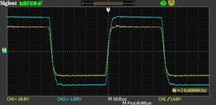
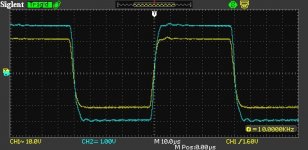
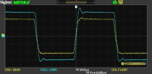
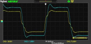
I have attached some of the 10 kHz square wave testing results. Yellow is the waveform on the primary, blue is the waveform on the secondary. Overall bandwidth of the amp is set by the Jensen input transformer, so I can't easily make the edges any sharper. The input transformer is essential to the phase splitting in this amp. Kinda blows my mind that these edges could be sharper. This Plitron transformer has absurd bandwidth.
First is 8 Ohm resistive load only, second is 0.1uF in parallel, third is 0.47uF in parallel, and fourth is 2uF in parallel. The output stage seems to take some pretty nasty loads like a champ.
Attachments
One advantage of a soundcard type spectrum analyser that goes to 96kHz bandwidth is that resonances above 22kHz can be observed if they start to come out of the noise floor (whereas you can miss seeing them in a normal digital scope waveform unless they become substantial).
Had you changed the wiring or circuitry since you observed the ad hoc parasitic oscillation?
I'd be a bit concerned about the FET gate in the 300V regulator due to Vgd voltage transients coupling through to influence Vgs via Cgd.
Do you have cathode current sensing in the circuit for each KT88 ?
Had you changed the wiring or circuitry since you observed the ad hoc parasitic oscillation?
I'd be a bit concerned about the FET gate in the 300V regulator due to Vgd voltage transients coupling through to influence Vgs via Cgd.
Do you have cathode current sensing in the circuit for each KT88 ?
I have changed (improved) the wiring substantially and made many circuit changes since I observed the issues.
All FET gates are protected. The schematics are simplified and don't show protection diodes and stoppers but they are there. I've got 1k stoppers on the grids of the KT88s and 200 Ohm stoppers on the screens.
I have individual cathode sense resistors. I actually have one of those bias servo boards by Guido Tent setting the bias.
The driver bootstrap is needed to deliver the swing. It is applying *POSITIVE fb...so, how about keeping the bootstrap benefit of what is effectively 'extra B+', and do away with the PFB? A CCS plate load should have that effect... 🙂
cheers,
Douglas
cheers,
Douglas
- Home
- Amplifiers
- Tubes / Valves
- Plate Inductors in Unity Coupled Output Stage