Thanks for Your reply and for Your effort making an updated 192kHzz version.
Please be aware that I have not yet decided which filters to use, still learning and simulating.
(I believed I had plenty of time to find out waiting for the shipment (which took days, not 1-2 months as supposed)
- I will try to find out what delay is needed for through-core SPDIF at 192kHz.
Read a lot to find out which filters needs less resources, seems most of the usual filters are implemented as BiQuad and hence equal.
Other points of interest :
- I'm pretty sure the probe in Sigma Studio has some quirks, giving diverging results from time to time.
Question :
- When I simulate filters with slew, I get more phase distortion. Is slew needed on (not controlled) filters?
Please be aware that I have not yet decided which filters to use, still learning and simulating.
(I believed I had plenty of time to find out waiting for the shipment (which took days, not 1-2 months as supposed)
- I will try to find out what delay is needed for through-core SPDIF at 192kHz.
Read a lot to find out which filters needs less resources, seems most of the usual filters are implemented as BiQuad and hence equal.
Other points of interest :
- The SigmaStudio help document recommends to use double-precision for filters with cutoff frequencies near or below 10% of the sample rate, or when the Q is very high.
- The S/PDIF receiver works at sampling frequencies between 18 kHz and 96 kHz.
- I'm pretty sure the probe in Sigma Studio has some quirks, giving diverging results from time to time.
Question :
- When I simulate filters with slew, I get more phase distortion. Is slew needed on (not controlled) filters?
Why do you need to save DSP resources? Are ADAU1452 resources not enough for you to implement your tasks?Read a lot to find out which filters needs less resources,
It is quite possible that this is true.The S/PDIF input and output word lengths can be independently set to 16, 20, or 24 bits, S/PDIF input can autodetect word lenght.
- I'm pretty sure the probe in Sigma Studio has some quirks, giving diverging results from time to time.
If you do not need volume control using an external potentiometer, then this block can be removed from the project.- When I simulate filters with slew, I get more phase distortion. Is slew needed on (not controlled) filters?
I believe less use of computing power would give less noise. The ADAU1452 has more power than I will need for a long time.
Slew in volume should stay, but I dont think slew in filters are necessary
Slew in volume should stay, but I dont think slew in filters are necessary
The datasheet for the ADAU1452 says that they use 64-bit arithmetic with double approximation, word length of 32 bits. In the case of a power DAC, its noise level is at the level of 106 dB (A), which is equivalent to N = (106 dB - 1.76 dB) / 6.02 = 17 bits. Do you think that by performing calculations with 32 bits you are able to accumulate an error of 32 - 17 = 15 bits? I think your concern is unnecessary, since in this case it is the power DAC that limits us in noise, and not the calculations in the ADAU1452.I believe less use of computing power would give less noise. The ADAU1452 has more power than I will need for a long time.
I'm not worried about the accuracy or the available computing power, both are ample for my needs. The noise I refer to is electrical noise, as the more power used will give a rise in electrical noise (and thermal noise). I think it is very important to keep all noise down early in the signal chain.
I think it is not a trivial task to accumulate noise in the adau1452 to such a level that it can affect the output noise of the power DAC.I think it is very important to keep all noise down early in the signal chain.
I would not worry about noise in the adau1452. But I do not insist, it your business, I express my opinion, I may be wrong.
It seems to me that you do not know that in this circuit there are no low-signal DACs. In this circuit, direct synthesis of PCM into PWM signal is used. Then the PWM signal is amplified and covered by feedback to reduce distortion introduced by the PWM amplifier and the influence of unstable voltage of the power supply. That is, in fact, after the ADAU1452 there is a real power PWM DAC with local feedback on the PWM signal. I gave the results of measurements of such a solution in this thread.he noise I refer to is electrical noise, as the more power used will give a rise in electrical noise (and thermal noise).
https://www.diyaudio.com/community/threads/3-way-dsp-amp.415065/
The DAC receives a 24-bit signal with a sampling frequency of 192 kHz, i.e. at the input the DAC receives a signal with an SNR resolution of 24*6.02+1.76=146 dB(Fs), but at the output this DAC can produce a signal with an SNR resolution of 107 dB(A), and the noise level is limited by the PWM DAC circuitry itself, and not by the mathematics in the ADAU1452.
So in this case I would not worry about the mathematics in the ADAU1452 and would use those filters that are convenient for solving a particular problem. The noise limitations are in the power section of the DAC, and not in the mathematics of the ADAU452.
Today I tested the plates and found a delay for 192 kHz. It turned out to be 54 samples.- I will try to find out what delay is needed for through-core SPDIF at 192kHz.
I updated the folder with files for Sigma Studio in the first post, a project at 192 kHz with the correct delay was added to the folder.
Thanks!
I've fallen into the big, deep hole of digital filtering, linear phase, FIR vs IIR, RIIR and so on. Reading the forums also made me rethink the speaker boxes. Life was easier without all the options available through software simulations....
Plan now is to lobotomize a pair of XTZ speakers just to get Your plates tested.
Keep up the good work.
Two plates available.
I have assembled two more plates.
I don't plan to collect any more of these plates in the next two months.
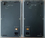

Performance parameter:
• Output power: 100 W per channel, R load = 4 Ohms.
• Speaker impedance: 4 - 8 Ohm (2Ohm – max 50W)
• Frequency response: 20Hz - 20kHz
• THD -3dB: less than 0.005% on 8Ohm load, and less than 0.01% on 4Ohm load
• SNR: 108dB(A)
• Spdif Input: 16-32bit 44.1-96kHz
• Spdif Output: 16-32bit 44.1-96kHz
• I2S Input: 16-32bit 44.1-192kHz
• Power supply: 100V-240V, 32V/11A
• Consumption power: Idle mode 15W, sleeping mode 4.5W
• Efficiency - 80%
The ADAU1452 are flashed with a starter program - 3Way FIR 48kHz. The folder with files for Sigma Studio is attached to the first message of this topic.
The plates come with a programmer on the CYC68013A chip and an optical receiver for remote volume control.
Those wishing to purchase such plates, write in private messages.
The price of the entire set is 390 US dollars.
Delivery to Europe and America is at my expense. Delivery to islands or other distant places is negotiated separately.
Payment via Payoneer.
I have assembled two more plates.
I don't plan to collect any more of these plates in the next two months.


Performance parameter:
• Output power: 100 W per channel, R load = 4 Ohms.
• Speaker impedance: 4 - 8 Ohm (2Ohm – max 50W)
• Frequency response: 20Hz - 20kHz
• THD -3dB: less than 0.005% on 8Ohm load, and less than 0.01% on 4Ohm load
• SNR: 108dB(A)
• Spdif Input: 16-32bit 44.1-96kHz
• Spdif Output: 16-32bit 44.1-96kHz
• I2S Input: 16-32bit 44.1-192kHz
• Power supply: 100V-240V, 32V/11A
• Consumption power: Idle mode 15W, sleeping mode 4.5W
• Efficiency - 80%
The ADAU1452 are flashed with a starter program - 3Way FIR 48kHz. The folder with files for Sigma Studio is attached to the first message of this topic.
The plates come with a programmer on the CYC68013A chip and an optical receiver for remote volume control.
Those wishing to purchase such plates, write in private messages.
The price of the entire set is 390 US dollars.
Delivery to Europe and America is at my expense. Delivery to islands or other distant places is negotiated separately.
Payment via Payoneer.
It turned out that using the All Pass filter to compensate for the LR24 phase does not allow you to get a phase-linear filter.I implemented your proposal in Sigma Studio and it is more rational than the delay line.
Below is the result of measuring the impulse and the step response of the sum of three bands of the subtractive crossover LR24 with All Pass filter.
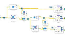
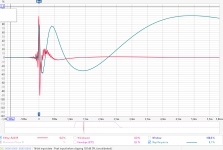
To obtain a linear phase of the sum of all three bands of the subtractive crossover, it is still necessary to compensate the phase using a delay line, this is the only way I was able to obtain a phase-linear crossover.
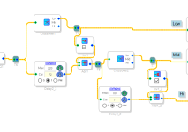
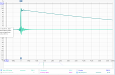
I updated the projects for Sigma Studio in the first post, now there are two types of subtractive crossovers with linear phase and non-linear phase.
Thank You for checking and measuring the step and impulse response in post #33, and for the updated project files.
Please keep up the good work, and continue to offer similar products to the DIY community
Please keep up the good work, and continue to offer similar products to the DIY community