No experience with HIFI ribbons, but IME thin membranes in general including cone/dome/textile driver membranes can handle the very fine water and alcohol based cleaners when very fine mist sprayed; with hydrogen peroxide seeming to dissolve dust, skin related prints, smudges, etc. and alcohol for very fine dirt, etc., plus leaves a higher gloss finish and both can be blown off/vacuumed at very low pressure. Why I prefer hydrogen peroxide overall though is it leaves a superior film that inhibits dust sticking to it vs alcohol, at least in the home, etc.; never have felt the need to try it in a harsh environment though, so YMMV, etc..

I have an example of using an asymmetric crossover to compensate for delay (the part on group delay was part of the other discussion).
- https://www.diyaudio.com/community/...hnique-for-horn-out-front.419357/post-7832834
- https://www.diyaudio.com/community/...hnique-for-horn-out-front.419357/post-7832834
Can you explain, or point me to something that explains, driver phase relationship in VituixCad?I have an example of using an asymmetric crossover to compensate for delay (the part on group delay was part of the other discussion).
- https://www.diyaudio.com/community/...hnique-for-horn-out-front.419357/post-7832834
I'm not gonna lie, I don't really understand the phase graph. I do understand what phase is, how it affects the crossover, and how it affects imaging. I plan to keep this nearfield monitor for a long time so I'd like to get the phase right for imaging purposes.
If you cannot read my mouse writing I can actually put text in. I am just lazy and do this all the time at work. Its all engineers so everyone can read everyone else's engineering chicken scratch
Attachments
Interesting! I understand the 'physics of the situation', yet the measurements don't seem right to me. 
Phase between adjoining drivers should normally follow each other. They can be together or separated by a fixed amount, but together is OK for a one measurement per driver crossover. 10 or 20 degrees either way is OK. They only need to do this while both drivers are within roughly 20dB of each other.
The following plots are all showing phase.
Here's an example of a 1kHz second order Linkwitz Riley low pass filter for a woofer (lower trace), then bring the woofer forward by 1/4 wavelength (upper trace, delay added)..

Now take that (upper trace) and increase to fourth order (lower trace)..

Now comparing the first and last, ie the normal filter and the increased filter with delay. You can see they are comparable in phase in the 500-2kHz region..

The following plots are all showing phase.
Here's an example of a 1kHz second order Linkwitz Riley low pass filter for a woofer (lower trace), then bring the woofer forward by 1/4 wavelength (upper trace, delay added)..
Now take that (upper trace) and increase to fourth order (lower trace)..
Now comparing the first and last, ie the normal filter and the increased filter with delay. You can see they are comparable in phase in the 500-2kHz region..
Last edited:
I just don't understand the graph is what I was trying to sayInteresting! I understand the 'physics of the situation', yet the measurements don't seem right to me.
Thanks for explaining. I see now.Phase between adjoining drivers should normally follow each other. They can be together or separated by a fixed amount, but together is OK for a one measurement per driver crossover. 10 or 20 degrees either way is OK. They only need to do this while both drivers are within roughly 20dB of each other.
The following plots are all showing phase.
Here's an example of a 1kHz second order Linkwitz Riley low pass filter for a woofer (lower trace), then bring the woofer forward by 1/4 wavelength (upper trace, delay added)..
View attachment 1384409
Now take that (upper trace) and increase to fourth order (lower trace)..
View attachment 1384408
Now comparing the first and last, ie the normal filter and the increased filter with delay. You can see they are comparable in phase in the 500-2kHz region..
View attachment 1384407
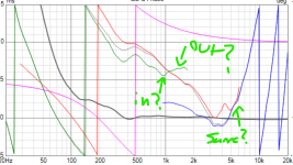
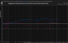
One other question. Here are two graphs. The blue measurement is a total system compiled of 3 drivers and 1 port. I see 4 phase shift lines where they cross over. This makes total sense to me.
The yellow one is a measurement I took of a Zaph 5" driver. I see what seems to be 2 phase shifts. Why is this? This does not make sense to me.
Attachments
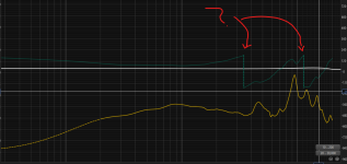
The crossing over you point to with the arrows is nothing. It just means the graph ran out of space and started again at the other side. You can attempt to remove some of this by applying delay.
Hey there, I probably have some helpful input on this but I'm at a concert reading diyaudio so not now. Just wanted to say I think your approach toward this looks like someone that's going to make some good speakers. Not sure about this idea but I wanna check out out another day.
@GM I use diluted isopropyl to clean up treated (with PVA / latex based polymer) surrounds, textile domes and cones. It temporarily dissolves the surface treatment and renews the visual appearance if done carefully. It works very well on Morel drivers that attract ALOT of dust. Before this, I first use some blue painters tape to remove larger particles by dabbing the tape VERY LIGHTLY onto the debris. It can make a crusty, awful looking dome appear as new.
Sorry for the off topic post. Just thought its valuable info.
Sorry for the off topic post. Just thought its valuable info.
Yes but not nothing nothing, it's a phase rotation, on a phase graph. It doesn't mean anything other than that the driver does not have a flat response, which of course it doesn't.The crossing over you point to with the arrows is nothing. It just means the graph ran out of space and started again at the other side. You can attempt to remove some of this by applying delay.
- Home
- Loudspeakers
- Multi-Way
- Planar Horn Research - Findings