failing due to THD at -105dB instead of the usual -115dB. Degree? measurable using std lab equipment such as an AP analyser. Same goes for capacitors and inductors. Even speaker binding posts with ferrite magnetic materials can give measurable distortion. Why is this so controversial? We have tons of measurements on this and may publish at some point. meanwhile, remember that absence of evidence is not evidence of absenceThat would be true of every component, passive or active. The real question is one of degree. That makes the statement above meaningless without numbers and specifics.
Misapplication of a component type often results in fireworks. Was this failure specific to resistor nonlineariety or just a misapplication?
It's not controversial THAT components cause distorion. It's questionable that the result is audible, when even trained listeners have trouble detecting 1% with special test signals. Today's analyzers give us incredible microscopes with which to look at distortion. But that ability often clouds the practical nature of the problem. -105dB might be considered a fail, but then, we have the transducer with distortion products at least 65 dB higher. Yeah, you can debate spectrum if you like, it's still 65 dB higher, at a Minimum, hovering around 1%. And yes I know about the exceptions, but this is reality. Then we have the problem that with distortion products 40dB below a sine wave test signal, how is music, that must be rich in harmonics at that level and higher, sound? Apparently not bad, because audiophiles are happily listening to that kind of distortion every day.failing due to THD at -105dB instead of the usual -115dB. Degree? measurable using std lab equipment such as an AP analyser. Same goes for capacitors and inductors. Even speaker binding posts with ferrite magnetic materials can give measurable distortion. Why is this so controversial? We have tons of measurements on this and may publish at some point. meanwhile, remember that absence of evidence is not evidence of absence
The we have the recorded signal itself. Microphones are not anywhere near THD at -115dB, so that distortion is baked in. If you love analog everything, we could talk about tape with an amazing array of distortion types. If you like vinyl, you can add yet more. If you prefer the digital path, great, until you get to your tube amp and speakers. All if it is already there. There's simply no improving anything audibly by reaching for another 10dB when you're at -105 alredy.
I'm not saying that -115dB isn't a fine goal, but you cannot expect that wonderful figure to be maintained microphone to speaker in any system. At which point I question why -105dB wasn't good enough.
I highlighted the problem here. "Clean sounding" is undefined and subjective. This is the point where someone needs to post proof, data taken scientifically and with controls, that resistors even have a sound at all.Hi, everyone. Lets try this dilema then. I have only two set of resistors, cant by other. So, put the type of resistor that is the more stabil one and clean sounding as first resistor on dac board where I2S come in, or as last before dac chip? Im talking about the 22 Ohm resistors on the board,. I try to keep this easy, but I see this post taking of now. AND, that is ok, alot to learn here for us all I think ( : Frank
No specifics given though. And again, no actual proof other than they might measure differently.Well he plausibly explained how two different resistors could sound different somehow in a specific application. But the general claim I really want explained is how said resistors have the predictable effect wherever they are used in a signal path. Of all the various points in circuits at different signal levels, with different currents, in filters, in attenuators, in tuned circuits , in your mothers cole slaw, they always make things warmer or more defined or less salty.
I can not enlighten you on that one ( : As much as I can not enlighten you why two different USB cables can sound different. Its only zero ( 0 ) and ones ( 1 ). But people hear diffrenc, so enlighten me. FrankThis is what confuses me, you are talking about a resistor in the digital domain, not the audio circuits. I don't follow how a resistor affects the sound in the digital circuits. Please enlighten me.
I feel that the almost complete absence of formal ABX testing in the audio industry is somewhat of a death blow to the religion of/belief in magic audio components. If manufacturer 'X', for example, made an interconnect that was so much better than the rest, their marketing department would be falling over themselves to set up such tests. Similarly for discreet components, green CD pens, 'Burn-In' services, cable risers, acoustic paint, etc. etc...
They want to hear a difference, so they hear a difference. Easy as that.I can not enlighten you on that one ( : As much as I can not enlighten you why two different USB cables can sound different. Its only zero ( 0 ) and ones ( 1 ). But people hear diffrenc, so enlighten me. Frank

Some Thoughts Regarding Spectral Analysis:
We may need to take care regarding HD measurements of sine waves at -110dB as representing what actually occurs when music plays. For one thing, there are usually unstated assumptions about DUT linearity, time-invariance, and or stationarity being no more than weakly inconsistent with mathematical theory. For one other consideration, IMD with music signals is likely to be considerably higher level than measured HD. Maybe think about how many individual frequencies are present at once in a 100 piece orchestra playing in tutti?
Regarding one of the links in my previous post, as the ESS slides show, not all distortion and noise (particularly signal-correlated noise) tend to show up in an easily interpreted way on typical audio FFTs. The more points in an FFT, the better the frequency resolution and the less noise per bin, but we may be more likely to overlook DUT time-variant behavior clues.
Perhaps something else to consider is that with most spectral analysis, phase information is discarded. What about crest factor of distortions and or noise (including signal correlated noise), doesn't matter, not ever?
Regarding Test Conditions:
Audibility might depart more than one might expect if working from an assumption that HD arises from a slight fixed curvature in some system's transfer function. An audio amplifier under laboratory test conditions might appear to be no more pathological than a slight time-invariant nonlinearity. What about in some home EMI/RFI environment? What about when ground loops are not carefully avoided? IME listening tests are the gold standard for what's really audible under complex conditions.
A Real-World Example of One Particular Observed Distortion:
Relative to devices more complex than most typical audio amplifiers, things like modern sigma-delta DACs can produce all sorts of strange noises and distortions. Still recommended to carefully consider what the ESS presentation is saying about their findings and suspicions.
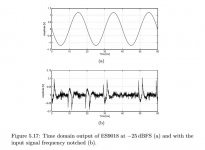
Don't know if anyone isn't familiar with ESS Hump Distortion as viewed via AP analyzer. If not, I can provide links to some of the discussion at ASR. The AP view may seem rather benign. Viewed in the time domain its appearance is much more suggestive of what the distortion/noise might sound like if ever audible. Attached is a time domain residual view shared by Scott Wurcer.
Doesn't look all that much like a time-invariant, weakly-nonlinear system to me.
We may need to take care regarding HD measurements of sine waves at -110dB as representing what actually occurs when music plays. For one thing, there are usually unstated assumptions about DUT linearity, time-invariance, and or stationarity being no more than weakly inconsistent with mathematical theory. For one other consideration, IMD with music signals is likely to be considerably higher level than measured HD. Maybe think about how many individual frequencies are present at once in a 100 piece orchestra playing in tutti?
Regarding one of the links in my previous post, as the ESS slides show, not all distortion and noise (particularly signal-correlated noise) tend to show up in an easily interpreted way on typical audio FFTs. The more points in an FFT, the better the frequency resolution and the less noise per bin, but we may be more likely to overlook DUT time-variant behavior clues.
Perhaps something else to consider is that with most spectral analysis, phase information is discarded. What about crest factor of distortions and or noise (including signal correlated noise), doesn't matter, not ever?
Regarding Test Conditions:
Audibility might depart more than one might expect if working from an assumption that HD arises from a slight fixed curvature in some system's transfer function. An audio amplifier under laboratory test conditions might appear to be no more pathological than a slight time-invariant nonlinearity. What about in some home EMI/RFI environment? What about when ground loops are not carefully avoided? IME listening tests are the gold standard for what's really audible under complex conditions.
A Real-World Example of One Particular Observed Distortion:
Relative to devices more complex than most typical audio amplifiers, things like modern sigma-delta DACs can produce all sorts of strange noises and distortions. Still recommended to carefully consider what the ESS presentation is saying about their findings and suspicions.
Don't know if anyone isn't familiar with ESS Hump Distortion as viewed via AP analyzer. If not, I can provide links to some of the discussion at ASR. The AP view may seem rather benign. Viewed in the time domain its appearance is much more suggestive of what the distortion/noise might sound like if ever audible. Attached is a time domain residual view shared by Scott Wurcer.
Doesn't look all that much like a time-invariant, weakly-nonlinear system to me.
Attachments
Last edited:
thanks for elaborating. The question of audibility is indeed complex and doing large RCT/DBTs is beyond our resources. We have worked with SenseLab at the Danish Force Technology on a DBT comparing our low distortion driver with variants having more distortion. The test had some obvious flaws (only listening to a band limited signal and the EQ used had some issues). Anyhow, the result was that the panel could not detect the difference with statstistical certainty but our team members could repeatedly - probably because we have trained our ears to listen after distortion artifacts. This test showed us how difficult the question is but if just one person can hear a difference consistently then it has our attention.It's not controversial THAT components cause distorion. It's questionable that the result is audible, when even trained listeners have trouble detecting 1% with special test signals. Today's analyzers give us incredible microscopes with which to look at distortion. But that ability often clouds the practical nature of the problem. -105dB might be considered a fail, but then, we have the transducer with distortion products at least 65 dB higher. Yeah, you can debate spectrum if you like, it's still 65 dB higher, at a Minimum, hovering around 1%. And yes I know about the exceptions, but this is reality. Then we have the problem that with distortion products 40dB below a sine wave test signal, how is music, that must be rich in harmonics at that level and higher, sound? Apparently not bad, because audiophiles are happily listening to that kind of distortion every day.
The we have the recorded signal itself. Microphones are not anywhere near THD at -115dB, so that distortion is baked in. If you love analog everything, we could talk about tape with an amazing array of distortion types. If you like vinyl, you can add yet more. If you prefer the digital path, great, until you get to your tube amp and speakers. All if it is already there. There's simply no improving anything audibly by reaching for another 10dB when you're at -105 alredy.
I'm not saying that -115dB isn't a fine goal, but you cannot expect that wonderful figure to be maintained microphone to speaker in any system. At which point I question why -105dB wasn't good enough.
One further issue with listening tests is that we do not have a zero distortion reference so the detection threshold is limited by the equipment used and the test will comapre different flavors of disortion and not disrtoion vs no distortion.
Our experience is that Pure harmonic disortion confined to the bass without generation of midrange IMD and you can get away with murder (10% or more is hard to detect). That changes when we get IMD of the more sensitive midrange. See for example https://purifi-audio.com/2019/12/12/imd/
Also two signals with the same power spectrum but different phase (AM vs FM) sounds different to most human ears which is not easily explained by masking theory: https://purifi-audio.com/2019/12/07/amfm/
Our coming 8" woofer has third harmonic whilst playing at 90dB being 80-90dB below the fundamental in the midband. Many amps dont make it that far. Note that this is measured with a hi quality condenser mic similar to mics used for recordings so mics are not the weak link. The mic is only 40cm away so the SPL is almost 100dB. A typical speaker is by far the limiting element in the audio chain and this is eactly what we are working on improving on. Our improvement on the amp side is mor e in the 'dimisnhing returns' category. The comments we get is that eg a small two way with our midwoofer sounds like a much much bigger speaker. This might be explained by the lower distortion similar to that of a large cone area speaker. Reproduced sound is still lagging much in comparison with the live performance and distortion from the chain may play a significant role here. More reasearch is much welcomed.
Hi, R1,R2,R3,R4,R5 and R6.
Frank, Didn't forget you. Sorry for the delay. Schematic shows R1 - R6 as 'transmission-line series-damping' resistors for some digital signals going into the dac. The signals are RF with some very high frequency components associated with the edges of the square waves. The resistors don't need to be special, although they should be non-inductive (metal film is good), probably not larger physical size than necessary, have leads as short as possible, and be physically close to other the devices they connect to. Usually such resistors are located at the output of the device that is driving the line, although that may vary some for nonuniform lines (where distributed damping may sometimes be more useful). In other words, the main thing is since we are dealing with RF signals here, it helps to use RF layout techniques and choose components suitable for RF use, rather than to treat the signals as one might wish to do for analog audio signals.
IMD is also measurable, and with many types of test signals. It is rarely higher than THD, other than in systems that involve dynamic gain change elements like dynamics processors, or in systems pushed towards some form of nonlinear high frequency limit. Even REW includes a battery of standardized IMD tests, but also includes the ability to run the type of "Spectral Contamination" tests that Deane Jensen outlined in 1988, but which has not been standardized. It can produce a test signal with 100s of components.Some Thoughts Regarding Spectral Analysis:
We may need to take care regarding HD measurements of sine waves at -110dB as representing what actually occurs when music plays. For one thing, there are usually unstated assumptions about DUT linearity, time-invariance, and or stationarity being no more than weakly inconsistent with mathematical theory. For one other consideration, IMD with music signals is likely to be considerably higher level than measured HD. Maybe think about how many individual frequencies are present at once in a 100 piece orchestra playing in tutti?
A complex, but known test signal partially addresses time-variant issues, as does a battery of tests done at multiple levels and durations. It's all possible.
Not really a problem. While it's true that longer FFTs "slow" response time, it's not necessary to use a lengthy FFT to discern distortion components. Also, the level of distortion is a very good indicator that further study is required. Once we're below about .05%, the job is more than done because nothing that low is audible. But again, multi-tone and multi-level testing is now possible, no reason not to do it.Regarding one of the links in my previous post, as the ESS slides show, not all distortion and noise (particularly signal-correlated noise) tend to show up in an easily interpreted way on typical audio FFTs. The more points in an FFT, the better the frequency resolution and the less noise per bin, but we may be more likely to overlook DUT time-variant behavior clues.
Phase information is not discarded in every FFT, just in certain forms like RTA. Swept/chirp analysis includes phase information. However, research has shown that phase distortion is extremely difficult to hear until it becomes relatively massive mid-band. That's something that literally would pop out of even a cursory FFT. Crest factor is included, as is noise. Signal correlated noise is actually already present because the noise floor is visible in even an RTA with signal, and we always test for noise without a signal too.Perhaps something else to consider is that with most spectral analysis, phase information is discarded. What about crest factor of distortions and or noise (including signal correlated noise), doesn't matter, not ever?
Well, I can't speak for equipment manufacturers, by in my work in broadcasting EMT/RFI is a huge and significant concern. Broadcast devices are always design for extraordinarily high RF fields, and when the aren't we know it immediately and take action. Home hifi is another story, but with the exception of WiFi and Cellular devices, RF fields in homes are quite low. WiFi and Cellular can be a problem, but again, it's not going to be subtle because of the character of those signals. They are also quite easily designed out. Testing is simple, but would depend on the manufacturer to perform. Wouldn't the tech running test have his iPhone in his pocket? Close enough! That's one that an audio manufacturer would want to look at because cellular is so prevalent, and getting stronger every day. 5G...etc. To not test for it would be opening the product to market failure.Regarding Test Conditions:
Audibility might depart more than one might expect if working from an assumption that HD arises from a slight fixed curvature in some system's transfer function. An audio amplifier under laboratory test conditions might appear to be no more pathological than a slight time-invariant nonlinearity. What about in some home EMI/RFI environment? What about when ground loops are not carefully avoided? IME listening tests are the gold standard for what's really audible under complex conditions.
You certainly could have a low distortion reference though, not zero, and it's still a good reference.thanks for elaborating. The question of audibility is indeed complex and doing large RCT/DBTs is beyond our resources. We have worked with SenseLab at the Danish Force Technology on a DBT comparing our low distortion driver with variants having more distortion. The test had some obvious flaws (only listening to a band limited signal and the EQ used had some issues). Anyhow, the result was that the panel could not detect the difference with statstistical certainty but our team members could repeatedly - probably because we have trained our ears to listen after distortion artifacts. This test showed us how difficult the question is but if just one person can hear a difference consistently then it has our attention.
One further issue with listening tests is that we do not have a zero distortion reference so the detection threshold is limited by the equipment used and the test will comapre different flavors of disortion and not disrtoion vs no distortion.
Glad to hear someone's testing IMD. But it would be interesting to know what IMD test signal is being used.Our experience is that Pure harmonic disortion confined to the bass without generation of midrange IMD and you can get away with murder (10% or more is hard to detect). That changes when we get IMD of the more sensitive midrange. See for example https://purifi-audio.com/2019/12/12/imd/
Remember that in a spectrum analysis, the result isn't "real", but a representation of "real". Spectrum analysis of an FM signal is just representational, the actual continual modulation isn't shown. Also, in the example, while the spectrums of the AM signal shows multiple modulating frequencies, but the time domain plot of the AM signal doesn't clearly show them, it shows one. That should result in just a pair of sidebands, not multiple. So I'm not sure what you're compairing there.Also two signals with the same power spectrum but different phase (AM vs FM) sounds different to most human ears which is not easily explained by masking theory: https://purifi-audio.com/2019/12/07/amfm/
Live performance and reproduced sound are two entirely different things, especially with two-channel stereo as the medium. As much as we'd like to compare them, and say our reproduced sound's goal is to match "live", they are as different as apples and meatloaf.Reproduced sound is still lagging much in comparison with the live performance and distortion from the chain may play a significant role here. More reasearch is much welcomed.
In the recording process, many different microphone types and designs are used. Condensers are not the only technology. One that has been increasing in popularity for decades, even though the technology is quite old, is that of the ribbon mic. Another is the dynamic mic. Both have clear nonlinearities that increase THD. That's something you may not know from the data supplied with the recording, but it's definitely there.Note that this is measured with a hi quality condenser mic similar to mics used for recordings so mics are not the weak link. The mic is only 40cm away so the SPL is almost 100dB.
High SPL is always the cause of increased THD, even with condenser mics. But you will also notice that few microphones specifications include THD, for several reasons, not the least of which is that it's not a low figure relative to that seen in amplifiers.
What??? Its been stated on this forum over and over again that resistors have distortion spectrum. And different materials vibrate differently (what a shock!) I hope you were kidding thereAbsolute nonsense, no such a thing as a warm or anything sounding resistor, they are all absolutely flat within the audible range so absolutely neutral.
Anybody saying otherwise is only trying to separate you from your money or has no clue or is pulling your leg.
@jaddie, Didn't mean to suggest that distortions can't be measured, or that noises can't. The practical problem is that in practice almost nobody seems to pay attention to vague clues. They look at one number, say, THD, see its -115dB or so, and declare that a device is transparent. What about the stuff that could have been measured but wasn't? What about the audibility of signal correlated noise, etc.?
I once talked to Earl Geddes about what we know about hearing, since Earl has published in that area. He said he thought we had a pretty good idea of what about 95% of the population can hear. He went on to say that to study the remaining 5% would require the development of new tests. His opinion that day, is all.
Another thing that I have a question about is 'threshold of audibility.' One of our forum members, Jakob2, is involved in perceptual testing. He explained something most engineers don't seem to understand: Thresholds of audibility are not hard limits, rather they are estimates of an average limit of audibility for a population. What I would like to add regarding such estimates as they apply to humans is that while a few hundred test subjects are enough to produce mathematically meaningful statistics, even large scale studies of humans such have been done in the field of medicine are often confounded by the huge variability of the billions of humans on earth. Some large studies have turned to be failures. How do we know psychoacoustics should be considered as exempt from similar errors?
Here is the basic problem forcing the questioning of psychoacoustics, as stated simply: We can perform every test an AP machine can do and still not predict exactly how an amplifier will sound. Why not? What are we missing? What else should we be measuring?
One example to consider: In a dac, the audio signal is approximately convolved with master clock close-in phase noise. That appears as widened spectral peaks of audio test signals. Widening is mostly seen around skirts near the bottom of a peak. The same convolution issue is a known and well-studied problem in radar where close-in phase noise can interfere with detection of small radar targets. As a noise phenomenon in dacs, noise is constantly changing as spectral components rise and fall. Can that cause dynamic masking that is being neglected in measurements? Some people insist close-in phase noise is inaudible, yet other people find that reducing it to very low level is perceptually detectable. Which is it? At what point is it inaudible on average to a population. At what point is it inaudible to every single human on earth? How sure are we that we know? And, how do you measure the level of close-in phase noise in equipment used for audibility studies?
Another observation: One thing we don't measure is the effective credibility of the stereo illusion of there being a virtual sound stage, including perception of width and depth (and for some people, height). There appear to be multiple factors that affect the illusion. IME a highly skilled listener can reliably discriminate between ultra low distortion amplifiers by listening for perceptual cues in the illusion of soundstage. Regarding possible masking effects by speakers, the most sensitive tests of that type require the use of large panel ESL speakers, Sound Lab being preferred. The room must be treated, etc. Any resonators or absorbers must be removed, which includes any unused speakers which act as passive damper/re-radiators. So far as I know, no published research has gone to the trouble of removing to the same extent various masking factors that may obscure true limits of audibility.
EDIT: One more comment, I think you may have missed the point by lrisbo about phase rotation. One can take a set of sine wave generators and display their amplitudes in an FFT. If you then adjust the phase of the sine waves without changing the amplitudes, after some settling time spectral peaks look the same. However, the time domain waveform has changed, and it can sound different. Perhaps more so for low frequency sounds. The effect is easy to show using Nelson Pass phase shift circuits to make 3rd harmonic distortion of a sine wave have maximum verses minimum crest factor. Sure it can be measured, but who is measuring it over at ASR when they jump to conclusions about audibility based on AP tests? How many engineers are fooling themselves about audibility based on their measurements? How many fooling themselves in other ways? Why is the conclusion always that the listener is the only one being fooled?
Last edited:
sure there are old mics that are used for single voices/instruments because they add warmth and colouring. However, a hi quality symphony recording uses an AB set of low distortion condenser mics - here all instruments are mixed acoustically before hitting the mics so this is where you need low IMD. The mics we use are better than -90dB at 100dB. They can go to 140dB SPL and then THD is perhaps -40dBIn the recording process, many different microphone types and designs are used. Condensers are not the only technology. One that has been increasing in popularity for decades, even though the technology is quite old, is that of the ribbon mic. Another is the dynamic mic. Both have clear nonlinearities that increase THD. That's something you may not know from the data supplied with the recording, but it's definitely there.
High SPL is always the cause of increased THD, even with condenser mics. But you will also notice that few microphones specifications include THD, for several reasons, not the least of which is that it's not a low figure relative to that seen in amplifiers.
Needs to be significantly better than what you compare it to. Conventional speakers produces lots of distortion so this good reference has not existed before perhaps now with our drivers or future versions.You certainly could have a low distortion reference though, not zero, and it's still a good reference.
It is a a carrier FM modulated by a another sine wave and this gives an infinity of sidebands according to modulation theory. The AM version has the phases of the side bands shifted, ie same amplitude spectrum but different phases resulting a AM modulated signal (which is not a pure sine due to the infinite number of sidebands).Glad to hear someone's testing IMD. But it would be interesting to know what IMD test signal is being used.
Remember that in a spectrum analysis, the result isn't "real", but a representation of "real". Spectrum analysis of an FM signal is just representational, the actual continual modulation isn't shown. Also, in the example, while the spectrums of the AM signal shows multiple modulating frequencies, but the time domain plot of the AM signal doesn't clearly show them, it shows one. That should result in just a pair of sidebands, not multiple. So I'm not sure what you're compairing there.
Already explained on post #47.If manufacturer 'X', for example, made an interconnect that was so much better than the rest, their marketing department would be falling over themselves to set up such tests.
They claim that they do. All they may have is just a perception of a difference. Whether they actually heard it or not needs to be evaluated for confirmation which they don't do.They want to hear a difference, so they hear a difference. Easy as that.
The troll fest started above.Are you getting your fine cuisine cooking tips from the burger flippers at McDonalds? Just curious.
Threads like this one only cause monstrous troll fests here
We may need to take care regarding HD measurements of sine waves at -110dB as representing what actually occurs when music plays. For one thing, there are usually unstated assumptions about DUT linearity, time-invariance, and or stationarity being no more than weakly inconsistent with mathematical theory. For one other consideration, IMD with music signals is likely to be considerably higher level than measured HD. Maybe think about how many individual frequencies are present at once in a 100 piece orchestra playing in tutti?
Somehow I can't stop thinking you have no idea of what you are talking about. It sounds like a bot outfitted with a random words generator in action.
- Home
- Design & Build
- Construction Tips
- Placement of resistors in signal path.