So wouldn't it also be the case that using the PA310 in a 40Hz VB design would significantly increase its power handling in the passband? Of course, when referring to passband, doesn't that really mean near the cut-off frequency of the system? If the PA310's power handling is reduced, then that will occur in both TL and VB designs. I'm just not sure that a TL system really holds any major benefits over and above a VB design, while introducing a lot of difficulties, which companies such as IMF and TDL expended a lot of effort to solve.Another thing - I've used the PA310 in a few builds. Using it in a 30 Hz design will significantly reduce its power handling in the passband - not a good thing for a driver designed for PA duty. Even the ~40 Hz tuning that I aimed for in some of my designs for it was a bit low for it.
The TL designs that I am familiar with are the very opposite of efficient. That's taken from the manufacturer's own published data, and not simply some theory or other.The TL design is incredibly efficient! These are observationa from experiments rather than theory.
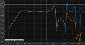
That's an impressive one-note peaky response, followed up by some wonderfully large (20dB or so) resonance peaks that need to be tamed. There's certainly a lot of acoustic output, but not all of it is good.View attachment 1462589
~200cm2 pipe crossection in a 230cm pipe (with driver positioned to avoid the second resonace)?
Thanks for the additional graphs! So here's the thing I wanted to discuss. If your design peaks at 101 dB at Xmax, our design are TWO order of magnitude apart in efficiency!
That part has me quite worried about where all that "extra" efficiency is coming from. The driver is rated at around 84dB for 2.83V, and as it's a 4-ohm load it's getting 2W of power. Where is that extra 16dB coming from, which represents a factor of 40 or so. I wish that the IMF/TDL TLs of old had that sort of efficiency quotient underpinning their TL response but, unfortunately, they didn't. I'm really unsure as to how such a small driver can generate such high output.My pipe-sub peaks at 100 dB @ 30 Hz with 1.0 W input. At Pmax/Xmax, it will produce well over 120 dB around 30 Hz! All with a single-driver UM8-22 and no signal conditioning apart from a standard subwoofer LP @ ~100 Hz.
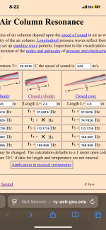
Maybe the long pipe design isn't really a TL design, but more of an organ-pipe resonance type of effect? Certainly, with the SPLs that you are quoting, they vastly exceed what the driver can achieve within its linear-displacement operating range. With a pipe that is L=2.3m long and closed at one end, the fundamental resonance frequency is equivalent to f = 343/(4xL) = 37Hz. That seems to coincide in an uncannily close way with your system. So, maybe it's not a TL that's been built, but an OP (organ pipe). I think that helps to explain the high output capability.I'm able to power my entire system (pipe-sub and pipe-tops) with a standard 18 V battery and a tiny Class D amplifier playing at impressive sound levels continously for more than one day. The TL design is incredibly efficient! These are observations from experiments rather than theory.

That's an impressive one-note peaky response, followed up by some wonderfully large (20dB or so) resonance peaks that need to be tamed. There's certainly a lot of acoustic output, but not all of it is good.
Tune it lower and taper the TL shape (or use a big vented reflex) so the higher frequency resonace spikes are based on a shorter internal length and the fundametal is ‘flatter’ (wider, smoother bandwidth and XO region)
But that doesn’t allow for the unique appearance and clever pipe construction (unless the last 1/2-2/3 were replaced with a smaller pipe crossection that didn’t produce excessive air velocity?)
Last edited:
That part has me quite worried about where all that "extra" efficiency is coming from. The driver is rated at around 84dB for 2.83V, and as it's a 4-ohm load it's getting 2W of power. Where is that extra 16dB coming from, which represents a factor of 40 or so. I wish that the IMF/TDL TLs of old had that sort of efficiency quotient underpinning their TL response but, unfortunately, they didn't. I'm really unsure as to how such a small driver can generate such high output.
Maybe the long pipe design isn't really a TL design, but more of an organ-pipe resonance type of effect? Certainly, with the SPLs that you are quoting, they vastly exceed what the driver can achieve within its linear-displacement operating range. With a pipe that is L=2.3m long and closed at one end, the fundamental resonance frequency is equivalent to f = 343/(4xL) = 37Hz. That seems to coincide in an uncannily close way with your system. So, maybe it's not a TL that's been built, but an OP (organ pipe). I think that helps to explain the high output capability.
Sure, my Hornresp simulations might be way off, or not. I'm lookin into ways of verifying the results. However, the proper way would require a BIG anechoic chamber and calibrated reference microphones.
I have some ideas of measuring input-output transfer using a signal generator, oscilloscope and dB meter, but it would include my room resonances.
Sure, my inspiration comes from organ pipes, which are also quarter-wave transmission lines. However, I'm positively surprised how my design seems not to be a one-note woder, but offers a rather flat response over the intended frequency range.
Horn response simulations can be incredibly accurate if the port and the driver are close together so you can easily get a measurement that’s not out in the room ?
I don’t have an SPL meter to calibrate the reading with however, so the default settings are strange.
There’s also a filter on this ‘subwoofer ‘ amp at ~200 hz that I can’t defeat
I don’t have an SPL meter to calibrate the reading with however, so the default settings are strange.
There’s also a filter on this ‘subwoofer ‘ amp at ~200 hz that I can’t defeat
Attachments
At 40 Hz, the power handling in-band is higher than it is at 30 Hz, but it is still low. 50 Hz and up Fb with a flat passband seems to be the sweet spot for this driver, which is not surprising, considering that it's a 12" driver designed for PA duty. Parts Express recommends a 1.5 cu.ft. box tuned to 57 Hz.So wouldn't it also be the case that using the PA310 in a 40Hz VB design would significantly increase its power handling in the passband? Of course, when referring to passband, doesn't that really mean near the cut-off frequency of the system? If the PA310's power handling is reduced, then that will occur in both TL and VB designs. I'm just not sure that a TL system really holds any major benefits over and above a VB design, while introducing a lot of difficulties, which companies such as IMF and TDL expended a lot of effort to solve.
As I mentioned, the main advantage to me of using TL instead of Vb is that I get to choose where the resonances appear (by choice of box size and vent size) and I can change the location of the driver and vent to minimize their impact in the passband. With a basic Vb design, usually you're stuck with choosing Vb and Fb and hoping for the best. That might be ok if the vent is small, but for subwoofer duty the use of small vents are not recommended.
The IMF and TDL designs appear to be devoted more towards full range duty, and those that I've seen look like they're based on classical TL theory, not modern TL theory.
That part has me quite worried about where all that "extra" efficiency is coming from.
His model is based on 0.5*PI loading. To compare with other models, it needs to be changed to 2*PI loading. 2*PI loading is usually assumed by other modeling programs that don't offer the option of changing it.
Below is a simulation of the PA310 8-ohm driver in a VB enclosure with Vb=42.5litres and tuned to Fb=57Hz. A −3dB point of around 57Hz isn't all that bad for a driver designed for PA duties. It can produce almost 114dB with an input power of 60W re 8 ohms, while Xmax is only exceeded below 40Hz.At 40 Hz, the power handling in-band is higher than it is at 30 Hz, but it is still low. 50 Hz and up Fb with a flat passband seems to be the sweet spot for this driver, which is not surprising, considering that it's a 12" driver designed for PA duty. Parts Express recommends a 1.5 cu.ft. box tuned to 57 Hz.
I wonder whether anyone has done a study of a VB enclosure tuned in a fairly standard manner, with the location of the vent on the baffle varied to see how the vent resonances are affected? Looking at some reviews of VB loudspeakers in Australian Hi-Fi, it's quite apparent that some VB enclosures have quite significant and deleterious vent resonances, while other designs are relatively free of vent resonances and the colorations that they add.As I mentioned, the main advantage to me of using TL instead of VB is that I get to choose where the resonances appear (by choice of box size and vent size) and I can change the location of the driver and vent to minimize their impact in the passband. With a basic VB design, usually you're stuck with choosing Vb and Fb and hoping for the best. That might be ok if the vent is small, but for subwoofer duty the use of small vents are not recommended.
Last edited:
At the low frequencies of interest, wouldn't a near-field measurement, with the microphone 1) placed in the plane of the port opening, and 2) a centimetre or two near the woofer's diaphragm, give you usable results without an anechoic chamber?Sure, my Hornresp simulations might be way off, or not. I'm lookin into ways of verifying the results. However, the proper way would require a BIG anechoic chamber and calibrated reference microphones.
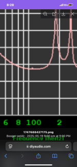
From my estimates, the fundamental resonance of the pipe is at 37Hz. For a pipe that is open at only one end, only the odd harmonics are natural frequencies (i.e., n = 1, 3, 5, etc.) The "second resonance", if it is being expected to be a natural frequency with n = 2, simply doesn't appear. This behaviour is clearly borne out by the results of the simulation carried out using Horn Response.View attachment 1462589
~200cm2 pipe crossection in a 230cm pipe (with driver positioned to avoid the second resonace)?
Maybe so. But the problem being that the speaker has two outputs that are both contributing equally to the total sound pressure, and they are separated by 1.7 meters. It becomes complicated to add up the two measurements, since the frequency response from driver and mouth is rather different!?At the low frequencies of interest, wouldn't a near-field measurement, with the microphone 1) placed in the plane of the port opening, and 2) a centimetre or two near the woofer's diaphragm, give you usable results without an anechoic chamber?
Also, the speaker is designed to be placed in a corner of a room, so that the TL mouth is radiating in 3 directions (instead of all 6 directions) from it's outlet. Meaning that a room is partly included as an extension of the TL design. Of course, it will still work in an anechoic chamber, but the mouth will kind of radiate directly into a void (absorption) .
I think that the main challenge with a straight TL design is that the 3rd harmonic in the TL is completely out of phase with the driver, hence creating distructive interference. The main reason I use an offset driver is to mitigate this problem.From my estimates, the fundamental resonance of the pipe is at 37Hz. For a pipe that is open at only one end, only the odd harmonics are natural frequencies (i.e., n = 1, 3, 5, etc.) The "second resonance", if it is being expected to be a natural frequency with n = 2, simply doesn't appear. This behaviour is clearly borne out by the results of the simulation carried out using Horn Response.
Anyways, the driver wills till produce all frequencies within the intended range, but the TL will of course not amplify all of them. As with all or most enclosures, the TL is designed to amplify the low-end, but at the same time not interfere with the driver for the higher notes, which is produces very well on its own through direct radiation from the diaphragm.
From my estimates, the fundamental resonance of the pipe is at 37Hz. For a pipe that is open at only one end, only the odd harmonics are natural frequencies (i.e., n = 1, 3, 5, etc.) The "second resonance", if it is being expected to be a natural frequency with n = 2, simply doesn't appear. This behaviour is clearly borne out by the results of the simulation carried out using Horn Response.
~37, 111, 185 (plus end correction)
The ‘second resonace’ @ 111hz doesn’t appear because the driver is sitting at its velocity node, but you can zoom in and see a trace of it
Attachments
Last edited:
I think that the main challenge with a straight TL design is that the 3rd harmonic in the TL is completely out of phase with the driver, hence creating distructive interference. The main reason I use an offset driver is to mitigate this problem.
Anyways, the driver wills till produce all frequencies within the intended range, but the TL will of course not amplify all of them. As with all or most enclosures, the TL is designed to amplify the low-end, but at the same time not interfere with the driver for the higher notes, which is produces very well on its own through direct radiation from the diaphragm.
The resonaces are ‘90 degrees’ out of phase with the driver. Multiples of full wave lengths are ‘completely’ out of phase. They are the big dips you would see if the port folded back over the driver like in a ‘tapped pipe/horn’ or many PA speakers .
If you Set the ‘path’ length to zero and you’ll see those frequencies in horn response
I wonder whether anyone has done a study of a VB enclosure tuned in a fairly standard manner, with the location of the vent on the baffle varied to see how the vent resonances are affected? Looking at some reviews of VB loudspeakers in Australian Hi-Fi, it's quite apparent that some VB enclosures have quite significant and deleterious vent resonances, while other designs are relatively free of vent resonances and the colorations that they add.
I've seen the results of at least one test that was performed like that, and yes, it showed that that the level of the vent resonances was affected.
I've got two Excel workbooks on my site that can be used to estimate the effect on a vented enclosure's response of these resonances
@Booger weldz That's right. Thanks for correcting me. I'm not sure how I somehow managed to overlook that 111Hz resonance that isn't being excited.~37, 111, 185 (plus end correction)
The ‘second resonance’ @ 111Hz doesn’t appear because the driver is sitting at its velocity node, but you can zoom in and see a trace of it
Yes, the frequency responses of the driver and the mouth of the pipe are quite different....the speaker has two outputs that are both contributing equally to the total sound pressure, and they are separated by 1.7 meters. It becomes complicated to add up the two measurements, since the frequency response from driver and mouth is rather different!?
The driver is behaving similarly to that depicted in the curve below.
The mouth of the pipe is behaving similarly to that depicted in the curve below.
It's not that difficult to add the two sets of results, taking into account the relative path length differences to the nominal listening position (without room effects).
One thing that I find interesting in the above is the broad, low-Q nature of the response at the mouth of the pipe of the first harmonic at approximately 37Hz. I would have expected that first pipe resonance (1st harmonic) to have been much higher in Q than it actually seems to be. All the other harmonics are much, much sharper, with much higher Q values.
That first resonance looks surprisingly like the Helmholtz resonance output of the port in a vented-box enclosure. The driver acoustic response is similar to that of the same driver in a vented-box enclosure. Your pipe radiator system seems to be a variant of a vented-box enclosure. It's surprising how similar in form are the simulations of a vented-box enclosure based on this driver to the pipe system response.
Last edited:
- Home
- Loudspeakers
- Subwoofers
- Pipe-sub version 2