I think it does something for sure. Whether or not it is audible is anyone's guess. Going to take some time off from building more absorption after I add some to ceiling and just try and enjoy the music and movies. It's gotta better than 90% of the rooms out there and I didn't need to shell out much for it!Thanks for your input ! 😎 And good luck for your 50Hz damping/trapping adventure...🙂
Posting some before and after graphs in bit.

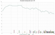
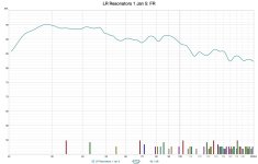
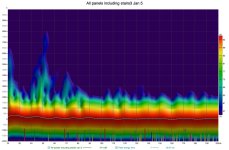
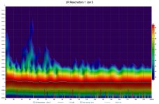
Ok, I took measurements before adding the tubes at all, then with tubes with polyfill in the neck (fistful), then with no polyfill in the neck, and then with all the tubes raised closer to the ceiling/corner of the wall and ceiling (about 16 inches higher and about 5 inches from the ceiling. Frequency response shows ver little change but the decay time show much more of a difference
Attachments


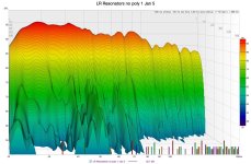
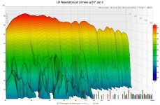
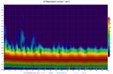
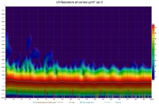
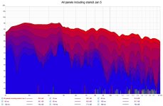
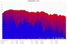
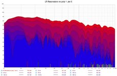

Yes, but the differences lie more with the time domain vs the frequency domain. Look at the 50hz region in all the other graphs.Oh, I have some problem to interpret correctly those diagrams - by lack of knowledge 🙄 - but I'd say that the best compromise seems to be the N°4, at the extreme right, if I only rely on the frequency response curve already... Right ? 🤔
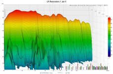
Yes, but the differences lie more with the time domain vs the frequency domain. Look at the 50hz region in all the other graphs.
Ah, OK - I see now : the 50Hz is correlatively minored with the FR curve, but it's much more obvious in the time-domain graphs, that's right. So you must notice a positive difference, I guess - even if it may not be so easy, because A/B-ing is impossible in this case !
T
Basically chasing graph porn at this point because like you said it’s impossible to A/B the difference. Our audio memory is about three seconds long…maybe I could enlist in three people per corner in my room to rest their hands over the mouth of the resonators, lol!So you must notice a positive difference, I guess - even if it may not be so easy, because A/B-ing is impossible in this case !
Basically chasing graph porn at this point because like you said it’s impossible to A/B the difference.
For sure : it's a difficult exercice... Where the measurement can help, when doable in good conditions !
maybe I could enlist in three people per corner in my room to rest their hands over the mouth of the resonators, lol!
Oho ! But their bodies themselves could act as unexpected sound dampers ! 😱😆
Our audio memory is about three seconds long…
Indeed, I think that I am certainly way under the 3 seconds 😕 ! That's why I do as often as possible A/B comparisons, maintaining all other parameters as equal as possible too, and you guess - or probably know - that it is not an easy task... And tell me : how many Audiophiles do that seriously 😉 ?
T
Damnit you’re right! lol!Oho ! But their bodies themselves could act as unexpected sound dampers ! 😱😆
Most are afraid of measurements and think their ears are magical 😉And tell me : how many Audiophiles do that seriously 😉 ?
I have to imagine it’s helping my bass as you can see the decay drops much faster right in the key area for things like kick drums, etc.
I might do 12 more when I have some time to measure again.
I might do 12 more when I have some time to measure again.
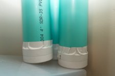
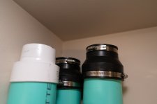
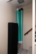
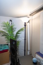
I don't remember if you posted a picture yet, but : how does it looks like ? I'm curious to see...
I mean : can these be hidden quite easily without detrimental attenuation in absorbing efficiency ?
T
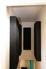
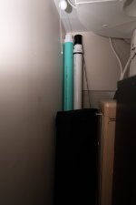
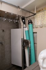
OH it's not pretty!!! The next phase will be trying to make this look much better. It's functional though. LR are open baffles I built with KEF Q100 drivers and GRS 15" woofers, all active.
Attachments
-
 7R500028.jpg169.8 KB · Views: 136
 -
 7R500027.jpg151.8 KB · Views: 134
 -
 7R500023.jpg135.8 KB · Views: 131
 -
 7R500018.jpg107.5 KB · Views: 132
 -
 7R500016.jpg267.5 KB · Views: 135
 -
 7R500015.jpg145.2 KB · Views: 136
 -
 7R500013.jpg311.8 KB · Views: 134
 -
 7R500012.jpg266.4 KB · Views: 127
 -
 7R500010.jpg287.6 KB · Views: 121
 -
 7R500009.jpg268.6 KB · Views: 140
 -
 7R500004.jpg271.1 KB · Views: 132
Maybe I don't understand what you mean but at the top of the pipes... 4in to 3 inch coupler. I do wonder if I would get more efficiency with a smaller nozzle opening.Where are the nozzles? Just curious. 😲
I think I remember reading in the paper that you sent me that the shorter nozzles worked better. What I'm curious about is the diameter but not just the diameter but the ratio between the body of the resonator and the neck. There is very little difference in this pvc design. 4" vs the 3 in" nozzle. I'm also very curious what would happen if the nozzle was cut at an angle. That would make the face or surface area of the nozzle opening quite a bit larger and perhaps give me more efficiency.The nozzle is critical to the design. As I commented earlier somewhere the nozzle is the most important part, more important than the volume because both diameter of the nozzle and the length are parts of the Helmholtz resonator equation, which I also posted earlier.
Yeah, this is all about the frequency created not the change in efficiency of the resonator. I read this and might try to drill some holes int he nozzles as this is supposed to add effeciency without me having to change anything else. It also seems to be a good idea to colocate the resonators as they become more effecient than the some of their parts if they are together. The paper didn't actually say anything about if they were tuned to the same frequency, however.
Vidhya_Rajendran_ARC_report_NBBJ_updated.pdf (uw.edu)
- Home
- General Interest
- Room Acoustics & Mods
- Pipe Dreams … 50hz Helmholtz resonator out of PVC pipe. Bass trap or money trap?