OK, I'm set at the equipment 🙂
Hahaha - I just touched the vol-pot housing, and now I have sound in both channels😀
Hahaha - I just touched the vol-pot housing, and now I have sound in both channels😀
Hmm, several possible places to find the error - also handling the tone control is giving the error...
Suspecting a wire....
Suspecting a wire....
Last edited:
The general approach - you give a constant sine wave to both channels, check it goes all the way to the input at the "good" channel (you see it at the output).
Then you start checking the "bad" channel with the probe, connecting the probe to the key points on the signal path - modules, pots, connectors, etc., until you find the place where it disappears...
I will drive from the office to home now - may take about an hour 😉
Then you start checking the "bad" channel with the probe, connecting the probe to the key points on the signal path - modules, pots, connectors, etc., until you find the place where it disappears...
I will drive from the office to home now - may take about an hour 😉
Think I got it - a pin wasn't soldered back in, on the tone control board, well 2 actually. I'd better go trough everything before putting it together, and maybe let it play for a few hours, to see (hear 🙂 ) how it's doing.

Perhaps I should try and see if I can adjust the FM tuner, as described in the manual, now I have the scope in house, even though I get a pretty good reception/sound (in the headphones) even with no antenna 🙂
Perhaps I should try and see if I can adjust the FM tuner, as described in the manual, now I have the scope in house, even though I get a pretty good reception/sound (in the headphones) even with no antenna 🙂
Hi Valery
Yes, seems like all is operating well now - I have had it playing about ½ an hour, without any problems, so now I try to reassemble the basics so that I can handle it and begin fixing lamps etc.
So - just a couple of loose wires 🙂
Yes, seems like all is operating well now - I have had it playing about ½ an hour, without any problems, so now I try to reassemble the basics so that I can handle it and begin fixing lamps etc.
So - just a couple of loose wires 🙂
I don't belive you - I'm sure you don't scare easily, Vasily 😉
This feels kind'a akward now - not many more "excuses" to bother you with my audio problems are left.
It has been an absolute pleasure, to be guided by you through this, rather challenging process, but you were always there, ready to help.
THANK YOU!
I plan to drop a line at Audiokarma, to finish my thread there properly, and if you don't mind I'll mention how helpful (and skilled) you are ?
No problem Ole, you are welcome. I like Pioneer as a brand and it was pleasure to communicate with you - it was a real teamwork 🙂
Let me know if you will need assistance
Cheers,
Valery
Let me know if you will need assistance
Cheers,
Valery
Thanks!
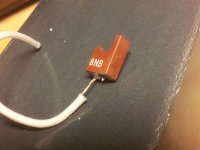
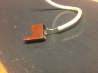
And whadda you know - I already have an issue 🙁 - the repaired STV4H (D5) broke off the wire again - I post a photo after this.
I hope it can take another repair, but I would like to hear if you have any experience with such problem, more of how deep can one dig into it to free more solder-wire. It seems the epoxy melts when I solder on the wire stub.
Also I consider - once I (hopefully) fix it, to apply some stabilizing cast on - perhaps some epoxy or the melted plastic of a glue gun?
Do you have an opinion on this?
a couple of pix on the way...
Attachments
Last edited:
Ummmf... this is a difficult one 🙂
Those diode combos were used by Pioneer widely, but I think not in production any more ((
I'm not sure how deep you can dig into it, well, probably a millimeter or two. Putting some compound or glue would be good, I think - just let it fully dry before you use it. Also a plastic pipe, that shrinks, when exposed to temperature, normally gives a good additional protection, keeping the whole assembly under certain tension (after it shrinks)...
Yes, not a good situation. I'll see if one of the solder specialists at work can save it. It would be unbearable if it can't be fixed at this point.
Yes, not a good situation. I'll see if one of the solder specialists at work can save it. It would be unbearable if it can't be fixed at this point.
Well, probably it would be possible to substitute - need to read a bit more about its parameters... I'll think about it... in parallel with you trying to fix it 😉
Well, probably it would be possible to substitute - need to read a bit more about its parameters... I'll think about it... in parallel with you trying to fix it 😉
Oh, great ! I saw a thread at AK by - I think echowars - had some interesting posts. I'll see and locate it again and send the link.
Meanwhile I will ask at AK for an opinion there as well - a lot of SX-threads have been on there.
Found this at AK - perhaps good for inspiration...
Replacing The STV-3H and -4H Diodes - Page 4 - AudioKarma.org Home Audio Stereo Discussion Forums
Replacing The STV-3H and -4H Diodes - Page 4 - AudioKarma.org Home Audio Stereo Discussion Forums
Another link....
http://www.diyaudio.com/forums/solid-state/83778-stv-4h-stv-3h-diodes-array-2.html#post1571976
Perhaps an STV-3H can do??? I have to read the post at AK again, some one used it as a replacement...
http://www.ebay.de/itm/Diode-STV3-H...deo_Elektronik_Verstärker&hash=item589290f061
http://www.diyaudio.com/forums/solid-state/83778-stv-4h-stv-3h-diodes-array-2.html#post1571976
Perhaps an STV-3H can do??? I have to read the post at AK again, some one used it as a replacement...
http://www.ebay.de/itm/Diode-STV3-H...deo_Elektronik_Verstärker&hash=item589290f061
Last edited:
The difference between STV4 and STV3 is actually the number of diodes inside the combo - 4 and 3 diodes respectively. We need 4.
From what I read so far, it looks like UF1004 behaves pretty similar to those Pioneer combos. I think UF1004 is not easy to buy these days, but UF4004 is easy to buy and thermally it is the same. So, as a solution - take 4 x UF4004, place side by side, connect them serially and seal with some electrically neutral compound - you get STV4-H equivalent.
From what I read so far, it looks like UF1004 behaves pretty similar to those Pioneer combos. I think UF1004 is not easy to buy these days, but UF4004 is easy to buy and thermally it is the same. So, as a solution - take 4 x UF4004, place side by side, connect them serially and seal with some electrically neutral compound - you get STV4-H equivalent.
- Status
- Not open for further replies.
- Home
- Amplifiers
- Solid State
- Pioneer SX-1080, after re-cap problem w. center voltage & idle current