I got fixed by my dear colleague - a certified solderer 🙂
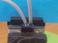
Sealed with Aerospace 3M 2216 3M aerospace and aircraft product catalog ? 3M US:Aerospace OEM:3M? Scotch-Weld? Epoxy Adhesive 2216 Gray Part B/A, 2 fl oz Kit, 6 per case
It will rest on my table for 24 hours - can't wait to finish 😀
Sealed with Aerospace 3M 2216 3M aerospace and aircraft product catalog ? 3M US:Aerospace OEM:3M? Scotch-Weld? Epoxy Adhesive 2216 Gray Part B/A, 2 fl oz Kit, 6 per case
It will rest on my table for 24 hours - can't wait to finish 😀
Attachments
I got fixed by my dear colleague - a certified solderer 🙂
Sealed with Aerospace 3M 2216 3M aerospace and aircraft product catalog ? 3M US:Aerospace OEM:3M? Scotch-Weld? Epoxy Adhesive 2216 Gray Part B/A, 2 fl oz Kit, 6 per case
It will rest on my table for 24 hours - can't wait to finish 😀
Looks very good. 3M glue and sealing products are excellent. I use some of them for gluing the video camera mounting plates to the helmet. After that you can remove it only together with a piece of helmet 😀
Looks very good. 3M glue and sealing products are excellent. I use some of them for gluing the video camera mounting plates to the helmet. After that you can remove it only together with a piece of helmet 😀
Haha - better put it in the correct place, then.
Do you have some nice videos uploaded somewhere?
The "never ending" story about a power supply 🙁
Well, now I can't barely contain myself 😡
I was just working on the scale lamp mount (another mod is necessary) while listening to FM, when I must have pushed Q4 so that it's heatsink touched Q1's heatsink: A little thump and no more sound
I took some readings on the PSU, but I didn't write them down, but noted that pins 20, 22, 23, 25, 27 and 28 were wrong, so I jumped to replacing Q1, Q2, Q3 and Q4, just guessing they could be damaged, from the proximity of the closest trans to the faulty voltage pins, however that made no diffrence.
The additional readings after replacement of the trans, may lead the direction of where to go from here?
The trans's I took out didn't appear to be damaged, judging from the control readings I took, which also corresponds with the fact that the error still exists with the same faulty voltage readings with the new trans's.
I sincerely hope you haven't had enough and still can find the time and give a hand 🙄
Well, now I can't barely contain myself 😡
I was just working on the scale lamp mount (another mod is necessary) while listening to FM, when I must have pushed Q4 so that it's heatsink touched Q1's heatsink: A little thump and no more sound
I took some readings on the PSU, but I didn't write them down, but noted that pins 20, 22, 23, 25, 27 and 28 were wrong, so I jumped to replacing Q1, Q2, Q3 and Q4, just guessing they could be damaged, from the proximity of the closest trans to the faulty voltage pins, however that made no diffrence.
The additional readings after replacement of the trans, may lead the direction of where to go from here?
HTML:
pin	act.	spec
7	+64	+62
8	-64	-62
16	+13	+13
18	+9	+ 7.5
19	+85	+76
20	+13	+23*
22	+22	+60*
23	+13	+23*
25	- 9	-23*
27	-17	-60*
28	- 5	-13*

D6-R9	+27	+24

q1b	+22.4	+60.6*
q1e	+21.7	+60.0*

q2b	+ 5.2	+14.8*
q2e	+13.8	+14.2

q3c	- 5.4	-13.0*
q3b	- 3.8	-13.6*

q5e	+13.5	+13.6
The trans's I took out didn't appear to be damaged, judging from the control readings I took, which also corresponds with the fact that the error still exists with the same faulty voltage readings with the new trans's.
I sincerely hope you haven't had enough and still can find the time and give a hand 🙄
Sent an unfinished message accidentally 🙂
Did you check the fuses? Looks like an overall PSU failure...
Normally, pins connected to the heatsink, are collectors, so you just touched collectors of the positive and negative regulators.
Meaning that PSU circuits most likely survived - the problem is somewhere to the left from Q1, Q4. Fuses, rectifier diodes...
Last edited:
I checked only the 10A fuse with DMM (good, obviously), and the 5 remaining only visually, and they, as the rest of the board, showed no sign of damage.
I will check on the fuses, and if they all are good, I will check on the D9 + D8,D10,D11, unless you advise otherwise.
Perhaps I should also lower Q1,Q4 all the way down, so that the heatsinks rest on the surface - I have left them a little elevated, in order to provide better cooling from below, but this gave the room for possible bending needed to make contact between them - the heatsinks I made are longer and wider than the originals, and were already leaning a little towards each other.
I checked only the 10A fuse with DMM (good, obviously), and the 5 remaining only visually, and they, as the rest of the board, showed no sign of damage.
I will check on the fuses, and if they all are good, I will check on the D9 + D8,D10,D11, unless you advise otherwise.
Perhaps I should also lower Q1,Q4 all the way down, so that the heatsinks rest on the surface - I have left them a little elevated, in order to provide better cooling from below, but this gave the room for possible bending needed to make contact between them - the heatsinks I made are longer and wider than the originals, and were already leaning a little towards each other.
Yes, it's better to keep the heatsinks secured. Just make sure the collectors of Q1 and Q4 are isolated from each other - either isolating transistors from the heatsinks or isolating the heatsinks from the chassis surface.
How is it going? Did you discover what happened?
Start measuring from the left of PSU schematic, moving to the right. Do you have those +/- 76 volts at the very left?
Haven't had access to my room yet (junior is staying over, and sleeps late 😉 ), but perhaps I should make some noise....
BTW I got real scared, when I saw your first incomplete answer 😱
BTW I got real scared, when I saw your first incomplete answer 😱
Haven't had access to my room yet (junior is staying over, and sleeps late 😉 ), but perhaps I should make some noise....
Hehe ))


BTW I got real scared, when I saw your first incomplete answer 😱
Ah, sorry - just touched the button by accident 😛
OK, I have tested the 5 remaining fuses - all are good.
I addition to the initial voltage readings from yesterday I have R7-R8:
So pins 20, 22, 23 ,25, 27, 28, Q1, Q2b and Q3 are giving incorrect values - not sure where to go from here?
I addition to the initial voltage readings from yesterday I have R7-R8:
HTML:
pin	act.	spec
7	+64	+62
8	-64	-62
16	+13	+13
18	+9	+ 7.5
19	+85	+76
20	+13	+23*
22	+22	+60*
23	+13	+23*
25	- 9	-23*
27	-17	-60*
28	- 5	-13*

D6-R9	+27	+24

q1b	+22.4	+60.6*
q1e	+21.7	+60.0*

q2b	+ 5.2	+14.8*
q2e	+13.8	+14.2

q3c	- 5.4	-13.0*
q3b	- 3.8	-13.6*

q5e	+13.5	+13.6

R7-R8	-85	-76
So pins 20, 22, 23 ,25, 27, 28, Q1, Q2b and Q3 are giving incorrect values - not sure where to go from here?
I'm afraid, the only way to move forward is to remove Q1, Q4 and probably Q2, Q3 as well and check them at least with an ohm-meter...
Most likely some of them are killed. Start with Q1, Q4 first.
Most likely some of them are killed. Start with Q1, Q4 first.
Well, first thing I did was exactly that: replacing all of Q1-4 - they are all brand new.
Noticeably none of the pulled were out of limits.
Noticeably none of the pulled were out of limits.
Well, first thing I did was exactly that: replacing all of Q1-4 - they are all brand new.
Noticeably none of the pulled were out of limits.
Ummmf... 😕
Then let's measure the voltage right at the collectors of Q1 and Q4 (referenced to ground).
Ahha! That means - R3 and R8 are not 2.2 ohm any more. Can you measure them (better independently - just un-solder one pin)?
OK - I believe I that was told over a AK, that the they were actually meant to be fuses, which makes sense, if it's correct - checking right away.
... hoping to find a 2.2 Ohm spare...
OK, got it. Reads 3.5.Ohm, but I suppose it's OK?
R8 was fried alright, but replacing it didn't help
... hoping to find a 2.2 Ohm spare...
OK, got it. Reads 3.5.Ohm, but I suppose it's OK?
R8 was fried alright, but replacing it didn't help
Last edited:
Something is wrong (obviously 🙂)...
On pin 19 we have +85V, on Q1c we have 21.6V. That means, we've got 63.4V over R3, which is 3.5 ohm.
That gives us 18A current through R3, that can't be the case - R3 would blow up under such current.
So, what is wrong in the equation? 🙂
Maybe there's no connection between pin 19 and left side of R3?
R3 was also fried, and after replacement these are the voltage readings:
Looking good again 🙂
, and we have music again 😀
It seems I keep messing up, but now I really hope I won't need to call on you more - even though I will miss the contact. But I suppose I shouldn't call it off yet - the bonnet is still off 😉
HTML:
20	+35.8	+33*
22	+63.5	+60*
23	+23	+23*
25	-23	-23*
27	-62.6	-60*
28	-13.5	-13*
Looking good again 🙂
, and we have music again 😀
It seems I keep messing up, but now I really hope I won't need to call on you more - even though I will miss the contact. But I suppose I shouldn't call it off yet - the bonnet is still off 😉
Last edited:
- Status
- Not open for further replies.
- Home
- Amplifiers
- Solid State
- Pioneer SX-1080, after re-cap problem w. center voltage & idle current