1. +LO -COM 40.6
2. +LO -VCC 1.508k
3. +VCC -COM 1.523k
4. +HO -VB 20.9
5. +HO -VS 1.661k
6. +VB -VS 1.656k
2. +LO -VCC 1.508k
3. +VCC -COM 1.523k
4. +HO -VB 20.9
5. +HO -VS 1.661k
6. +VB -VS 1.656k
Do you get the same readings if you reverse the probes for tests 1 and 4?
Do you still see a pulse on the output with Q729 bridged?
Do you still see a pulse on the output with Q729 bridged?
Same numbers even if I reverse probes.
When I hook up multimeter on speaker output channel voltage keeps dropping to 7v when red leds blinks voltage jumps to almost 14v and just keeps cycling like that.
O-scope shows a bit different this time, before bridging Q729, o-scope would show weird wave when led blinks and speaker output voltage changes. Now shows straight slightly fuzzy line and when led blinks whole lines jumps down and back again.
For transistors Q105- Q108, measuring from base to collector for each transistor, what's the lowest reading you get?
What value do you read from the base of Q105 to pin 14 of the 2092?
Remove R175 and measure the resistance from pin 10 to pin 11 again.
Remove R175 and measure the resistance from pin 10 to pin 11 again.
The 2092 appears to be defective assuming R176 is within tolerance.
Reading from the base of Q105 to the collector of Q105 should have read approximately the same as test #4 above. Do you still read 20 ohms from pin 14 to pin 15?
Reading from the base of Q105 to the collector of Q105 should have read approximately the same as test #4 above. Do you still read 20 ohms from pin 14 to pin 15?
Look at the diagram you posted. The collector of Q105 connects directly to pin 15. Does your boar differ?
R173 appears to be out of tolerance.
R173 appears to be out of tolerance.
As far as I can see it’s the same, when I was looking for capacitor and resistor values everything looked the same. I used other models as reference and layout is different.
Carefully follow the trace from Q105 collector to pin 15, checking every possible connection. Do you see any break?
Are you looking at the driver that's closest to the IC? almost touching D107.
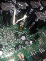
Check R175. It looks like it has a hole in it.
Check R175. It looks like it has a hole in it.
R175 is missing (as we removed) before that there is hole in pcb.
And yes I’m looking at the one that’s close to D107.
And yes I’m looking at the one that’s close to D107.
- Home
- General Interest
- Car Audio
- Pioneer D9601 repair
