Q105 KTC 1027 021
Q106 A1023 041
Q107 KTC 1027 021
Q108 A1023 041
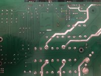
Well I measure whatever you ask e.g. collector pin 3 close to huge capacitors, base pin 2 in the middle.
Q105 pin 3 collector to pin 15 ~2.51 resistance,
Q105 pin 2 base (middle) to pin 15 reads reads nothing.
Q105 pin 3 (collector) to pin 14 reads 2.51k
Q105 pin 2 (base) to pin 14 reads 20.9.
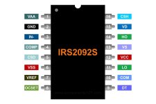
I use this pinout.
Q106 A1023 041
Q107 KTC 1027 021
Q108 A1023 041
Well I measure whatever you ask e.g. collector pin 3 close to huge capacitors, base pin 2 in the middle.
Q105 pin 3 collector to pin 15 ~2.51 resistance,
Q105 pin 2 base (middle) to pin 15 reads reads nothing.
Q105 pin 3 (collector) to pin 14 reads 2.51k
Q105 pin 2 (base) to pin 14 reads 20.9.
I use this pinout.
Attachments
Sorry.
Does that mean Q105 middle pin is collector?
Could you please explain? if yes then I messed it up…
Does that mean Q105 middle pin is collector?
Could you please explain? if yes then I messed it up…
What you need to do is to confirm all connections between the IC pins and the driver transistors and confirm that all resistors in that area are within tolerance.
You can't take anything for granted, especially when someone else tried to repair it before you got it.
Reinstall all resistors.
Lift terminals 11 and 14 of the 2092 to break their connection to the board and confirm that you still read low ohms between the same terminals (not the board) as you did previously.
Thank you Perry, I appreciate your time!
I will do, I’m just ‘diy’ing around’ and I learned a lot from you.
Should I remove the bridge on Q729 once everything is checked and resistors reinstalled?
I will do, I’m just ‘diy’ing around’ and I learned a lot from you.
Should I remove the bridge on Q729 once everything is checked and resistors reinstalled?
Not yet for Q729.
Do the solder connections look original on the output transistors or were they possibly replaced previously?
I'd conform that all gate resistors are within tolerance since it takes only seconds.
Post what you read on the lifted terminals of the 2092 when you get back to it tomorrow. (midnight there?)
- Home
- General Interest
- Car Audio
- Pioneer D9601 repair