Hi,
Does anyone know much about PT Too power supplies? Does anyone know how they work?
When searching the internet and asking on other forums, no-one seems able to help as if these are a complete mystery yet from looking at the circuit, it seems to be a very simple amplifier driven by a (complex looking) sinusoidal waveform generator..
I am wanting to revive my dead one which failed when I accidentally turned it on without the motor connected. Surely this would just mean rebuilding the TDA2004 amplifier circuit as I can't imagine any damage would go back further than this. Could this be correct? The opinion I get from people is that when a PT Too PSU is dead, it is dead forever but I just don't believe it..
Incidentally, one of the three PSUs I've amassed has all the chip identities intact so I can show all the CMOS chips that are in the circuit should anyone be interested - perhaps someone wants to clone it? Just let me know and I'll get snapping with my camera.
I'd be greatful for any help.
Nat
Actually just reading the chips won't get you very far, there's a fairly tricky circuit in there, the purpose of which is to achieve division by 8/3.
The problem could be the TDA 2004s, the coupling caps or the output transformers.
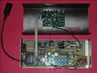
Check whether there are two sine waves at the two resistors on the left of the board (where the two black wires are soldered in in the attached phot). If so the CMOS generator is OK.
Next check whether there are two (higher magnitude) sine waves present on the left side of the two big caps between the TDA 2004s and the output trafos. If so the TDA 2004s are OK. If not the chips themselves are probably toast.
Lastly check whether the same voltages are present on the right side of the caps. If so the caps are OK and only the trafos remain as the source of the problem.
The problem could be the TDA 2004s, the coupling caps or the output transformers.
Check whether there are two sine waves at the two resistors on the left of the board (where the two black wires are soldered in in the attached phot). If so the CMOS generator is OK.
Next check whether there are two (higher magnitude) sine waves present on the left side of the two big caps between the TDA 2004s and the output trafos. If so the TDA 2004s are OK. If not the chips themselves are probably toast.
Lastly check whether the same voltages are present on the right side of the caps. If so the caps are OK and only the trafos remain as the source of the problem.
Hi Mark,
Many thanks for that. Actually, someone had suggested that you might know but I couldn't remember your name..
That all makes sense, working through the circuit - I had forgotten that the transformers are involved in getting the voltage up at the end. I will check through with an osciloscope as soon as I can.
As an aside about the circuit, are the two variable resistors at the TDA2004 inputs there to adjust the phase angle of the sinewaves and if so, can these be tweeked to lower motor noise?
Also, one of the three PSUs is working but running slow so could a simple renewal of the crystal help with this or is the circuit speed dependant on too may factors - CMOS chips should be quite reliable shouldn't they?
Thanks, Nat
No, there is no phase angle adjustment on the PT Too supply, nor any frequency adjustment. The two pots set the output amplitudes of the two waveforms.
The phase angle is set by the phase delay of one half of the MF10 filter chip and is dependent only on the clock speed fed to the chip. Since the clock is fixed, so is the phase delay.
As I said before, if you have two sine waves at the feed resistors for the TDA2004s then there's nothing wrong with the generator circuit.
I bought my PT-TOO 20 years ago and it still works perfectly.I had problems with power supply rectifier and 12v voltage regulator. Button shaped rectifier bridge is with too low current rating for p.s. circuit-replace it with bigger one. There are two open frame 10K presets near the TDA2004 stereo power amps-replace them with sealed cermet types.They define output voltage measured at din 5pins socket,which should be adjusted , as i was told by Pink Triangle people, to 90 V for 33rpm. I adjusted separate outut voltage for both windings to reduce motor vibration at 100 hz.For my motor sample it is90V/92V. My turntable runs0,6% slow but i was not able to improve it by crystal or chips replacement. On the contrary, i got even slower motor running with different parts. It is a matter for furher investigation. I advice soldering 275V varistor between P.S. transformer live and neutral since it makes real sound improvement. Insulate VDR leads with PVC tubing. There is a provision for battery operation on the P.S. din socket. I use 4VA 12V SLA battery charged by internal Pink power supply electronic with a simple Lm317T based charging circuit. Sound is slightly more open and firmer with less surface noise.Pink Triangle was a company with bad Q.C. and almost no after sales support. They had never answered my letters. But vital turntable parts ,especially platter, were well made and my turntable have given me neutral reproduction of my record collection. Power supply schematic would be very useful for PT-TOO owners.
Unfortunately I never finished tracing the PT Too supply circuit out completely. All I needed was to work out where I could take off the various logic levels for the speed control switching and where to cut into the circuit with a new generator module.
The phot I attached to the post above shows the wires attached at these points (plus the 12V PS takeoff).
I don't have the supply any longer it was returned to its owner after I replaced the electronics.
The phot I attached to the post above shows the wires attached at these points (plus the 12V PS takeoff).
I don't have the supply any longer it was returned to its owner after I replaced the electronics.
I still haven't had a chance to look at the PSU yet - I think that might be a Monday evening job..
I couldn't see an attached photo Mark, would you mind attaching it again please?
I wonder with the speed thing if it is also a case of replacing the resistors/capacitors to ensure that they are all correct values and so deriving the correct values from the chips, the filter chip especially. There are a few small caps around the crystal that may effect things over time.
All this hastle just because market forces/public opinion dictated the use of AC motors (so the story goes)! DC, their true philosophy, seems much simpler to maintain and adjust.
Those small upgrades sound a good idea after I've fixed it - is the DC supply you are using a DIY construction or the original Pink Triangle one Kamis?
I will also take some good photos of both sides of the boards for some future circuit tracing for people.
I have two very slightly different versions and they function slightly differently too. One version has a CA555CE (is that just a 555 timer?) and operates by 'keying in' a certain number of presses for each speed and stop - one press for 33, two for 45, three for Stop, click too slowly and it thinks you are just asking for 33. The other omits this extra circuitry and simply cycles though 33/45/Stop on each succesive press. The latter appears the older.

PT TOO PSU
Hi Mark - if you are still alive and get this. I'm in Brisbane and have just found my old PT TOO in excellent condition. Lost the PSU but have located one in Scotland which owner says not working. Do you repair these AC PSU's and if so happy to pay.
Hi Mark - if you are still alive and get this. I'm in Brisbane and have just found my old PT TOO in excellent condition. Lost the PSU but have located one in Scotland which owner says not working. Do you repair these AC PSU's and if so happy to pay.
A Different PT Too?
First post, so please excuse any mistakes.
I have a PT Too that I purchased ~ 1989 at KJ in London.
I now use it in Canada with a step-up transformer at the front end.
When I tried turning it on recently, I noticed that the entire platter was vibrating and that there was noise emanating from the motor.
Since the belt was loose (original) and the motor never oiled, I replaced both (original motor = 9904 111 04312). New motor = Premotec 9904 111 31813.
(Thrust bearing from Michael on order)
Unfortunately the vibration and noise continued.😕
A DMM on the motor windings was showing voltages at 180VAC at 33 RPM and ~ 45VAC at 45 RPM.
Having scoured the web, for info, I finally decided to sketch out the circuit to help troubleshoot. This is attached in .pdf. Note that it is incomplete - the control logic is not included and frankly I ran out of enthusiasm.
In the end it turned out that the voltages to the motor were severely distorted (yep even bought a scope). Turned out that the distortion was emanating from the 2nd integrator stage. A slight adjustment of VR1 cured this and now everything seems back to normal. I can only guess that VR1 was acting up as adjusting this full seems to create the same effect.
I am still testing the PSU with a car battery and the old motor and everything seems stable for now.
Regards
Figs
Attachments


Origin live in southampton UK sell DC motor conversion with PSU
Looks very good with different price points £££
Looks very good with different price points £££
It's a shame that the OL stuff measures so badly with drift over the course of a side, they lack thermal, voltage or current compensation.
When I opened one up, it appeared to be nothing more than basic voltage regulator to a DC motor. I then later got the middle range controller and it was nothing more than a better regulator and capacitors for another £120 or more increase in price. Both I'd bought to sell on so I never formed an opinon of how well they worked.
IIRC, the OL controllers used a cheap and cheerful 2 transistor design that does have a very basic current compensation similar to the ones shown near the bottom of the page in this link:
AB-026 : Sensorless Speed Stabiliser for a DC Motor - Precision Microdrives
They are dirt cheap to build, but not very accurate, and of course, no temp compensation. The OL controllers have reasonably nice cosmetics externally, but the PCBs remind me of projects I built as a teenager, using Radio Shack materials and etching the boards in my sink.😎
The more expensive one use a better LTP. But safe to say they ate still ****
Last edited by a moderator:
Thanks
Many thanks for this ef079295, really helpful. I am repairing one for somone, exactly the same. Bridge rectifier burnt out - I've yet to discover if any other damage has been caused by this.
Many thanks for this ef079295, really helpful. I am repairing one for somone, exactly the same. Bridge rectifier burnt out - I've yet to discover if any other damage has been caused by this.
First post, so please excuse any mistakes.
I have a PT Too that I purchased ~ 1989 at KJ in London.
I now use it in Canada with a step-up transformer at the front end.
When I tried turning it on recently, I noticed that the entire platter was vibrating and that there was noise emanating from the motor.
Since the belt was loose (original) and the motor never oiled, I replaced both (original motor = 9904 111 04312). New motor = Premotec 9904 111 31813.
(Thrust bearing from Michael on order)
Unfortunately the vibration and noise continued.😕
A DMM on the motor windings was showing voltages at 180VAC at 33 RPM and ~ 45VAC at 45 RPM.
Having scoured the web, for info, I finally decided to sketch out the circuit to help troubleshoot. This is attached in .pdf. Note that it is incomplete - the control logic is not included and frankly I ran out of enthusiasm.
In the end it turned out that the voltages to the motor were severely distorted (yep even bought a scope). Turned out that the distortion was emanating from the 2nd integrator stage. A slight adjustment of VR1 cured this and now everything seems back to normal. I can only guess that VR1 was acting up as adjusting this full seems to create the same effect.
I am still testing the PSU with a car battery and the old motor and everything seems stable for now.
Regards
Figs
- Home
- Source & Line
- Analogue Source
- Pink Triangle PT Too PSU revival/understanding