Hi
the separate power supply for my PT TOO is giving out 76v. The motor in the turntable is 110v max.
I thought I had a motor problem as it doesn't seem to have enough torque.
Can someone let me know what the correct output voltage is for this power supply ??
thanks in advance.
the separate power supply for my PT TOO is giving out 76v. The motor in the turntable is 110v max.
I thought I had a motor problem as it doesn't seem to have enough torque.
Can someone let me know what the correct output voltage is for this power supply ??
thanks in advance.
thanks but already tried. FF push the new dc motor which I'd dearly love but if I can fix this then at the moment that's the best I can hope for.
Not unusual to run a synchronous motor on a lower voltage in order to reduce vibration, but 76V on a 110V motor does seem rather low. Can you identify what type of motor this is? (I'm suspecting a Premotec or similar..) I'd figure 90 - 100V would be more reasonable.
I experimented extensively with lower voltages and noisy synchronous motors and found that some motors ran quite well at 70% or so of their rated voltage, but torque was greatly reduced obviously.
Sorry to hear that rather than provide the information to fix yours they just want to sell you one of their upgrades. Frankly I'm not too surprised.. 🙄🙄
I had a slightly used PT turntable (model now forgotten, and I've tried really hard to forget I ever owned it) in the early 1990s and the ruby in the inverted bearing shattered. Before that I had terrible problems with the dc motor based drive, it had the poorest speed stability of any table I have ever owned. (The motor was widely used in cheap Japanese belt driven tables of the time which had no speed stability issues, I had two controller boards and motors, both just as bad, clearly a design issue.) A shame because it clearly incorporated some interesting design innovations - inverted bearing, fairly heavy acrylic platter, and a honeycomb sub-chassis none of which were very common at the time. Because of a dispute between them and their distributor all American owners were left high and dry with no support from PT. I was not able to get parts to repair it and ended up selling it at a big loss to a fellow in the UK who wanted one and planned to have it upgraded.
I'd inspect your bearing, and also determine whether or not the motor needs some lubrication.
Can you provide any more detail about the supply - is it just a transformer and some resistors and caps or is an actual source that generates the driving voltages required? Could need a recap?
Can you take some pictures of the controller?
Last edited:
oh dear, sounds like you've had a bad experience with pt !!
I got mine through a friend along with the rest of a setup as a way to get into decent hifi !! the tt comes with a decent arm and cartridge and at the moment getting back up and running is the cheapest option.
the motor has the following on the back:
synchronous motor
990411131813
110v 50hz 250rpm
mb03 ? model number
1588
philips made in belgium
the power supply is a seperate box. I think it's the later of what you mention.
It's with my engineer at the moment but when the snow (yep we're snowed in over here!!) clears I'll see if I can get some photos.
The problems I've had are that sometimes when I switch it on it doesn't power up. Sometimes it gets going with a helping hand, sometimes it spins the wrong way !! . . Although it's not done this at the engineer's place which makes me wonder if I have a supply problem to the turntable power supply unit.
thanks so much for the info. I'll pass it on and see if we can sort something
Mark Kelly has worked on these (see link)-you might try contacting him, or perhaps he'll see this thread. Kevin, pictures of the PS are also on the below link.
FWIW, the VPI SDS starts out at full voltage, then drops down to a user-settable voltage for 'silent running'- I've generally run mine at 80v. Have no idea if this is applicable to your case, but there you are.
http://www.diyaudio.com/forums/analogue-source/120195-pink-triangle-pt-too-psu-revival-understanding.html
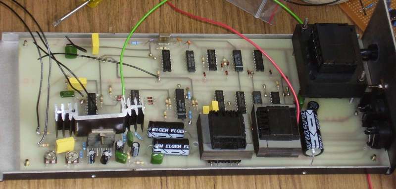
The two small pots on the right of the phot adjust the output voltage (one for each phase).
Ignore the extra wires attached to the top of the board, they were there so I could graft in a different quadrature generator which allowed adjustment of frequency, phase angle and cogging torque. Before you ask, no it is not available any longer and never will be again.
I had hoped I would see something that looked a little more professional, the level of quality IMHO is quite poor - not in keeping with the rest of the turntable design. The PCB looks very amateurish, and the poor execution leaves me questioning the quality of the design as well. The older version DC drive pcbs I had looked somewhat worse, but there were no mains level voltages present on that board. I don't think PT did electronics well at all...
Depending on how old this thing is it should probably be recapped, and I'd certainly see about boosting the voltage a bit. Note that you should try to adjust both phases so their output voltages are pretty close to the same. (90 - 100V depending on vibration)
I'd probably get some more reliable pots from the like of Bourns or similar as I've had some problems with similar pots in other devices - long term they're not that reliable.. IMHO
The fact that it sometimes starts and runs the wrong way could indicate that you are periodically dropping one of the phases or perhaps all the time? This could also explain the lack of torque.
Edit: Apparently the power source generates 100Hz for 33rpm and 135Hz for 45rpm.. So it might be possible to purchase a controller on eBay and modify it to produce the right output frequencies if this one dies.
Last edited:
IIRC the frequencies are 50.0 Hz and 67.5 Hz
That would make the most sense and is pretty standard these days, in the other thread referred to a poster mentions 100Hz at 33rpm.
There is at least one seller on eBay that offers an electronic controller that is supposedly good.
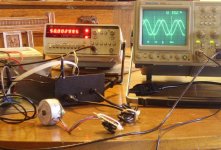
As per phot, 50 / 67.5 Hz operation is confirmed.
I can't remember the details of the PT Too circuit but I think it uses a pair of flip flops to achieve 50% duty cycle before the filters. That would explain why the frequency steps from 100 / 1325 Hz to 50 / 67.5 Hz.
I can't remember the details of the PT Too circuit but I think it uses a pair of flip flops to achieve 50% duty cycle before the filters. That would explain why the frequency steps from 100 / 1325 Hz to 50 / 67.5 Hz.
Attachments
Last edited:
That's good news for the OP as it makes life a lot simpler if he ever needs to replace that piece o' ****, err controller.. 😀 Lots of choices.
As per phot, 50 / 67.5 Hz operation is confirmed.
I can't remember the details of the PT Too circuit but I think it uses a pair of flip flops to achieve 50% duty cycle before the filters. That would explain why the frequency steps from 100 / 1325 Hz to 50 / 67.5 Hz.
There was a project "Variable Speed Turntable Drive" by Alan.C. Ainslie in Hi-Fi News and Record Review in June 1973. It consisted of a phase shift oscillator driving a capacitor coupled 10 watt r.m.s amplifier feeding the 6.3 a.c. secondary winding of a 1 amp rated transformer . The design was intended for use with a Thorens TD150 or a Connoiseur BD1 but was said to drive Garrard units with 115 a.c.volt motor drives.
The oscillator frequencies were 50 /67.5 Hz for 33 r.p.m /45 r.p.m. operation. The aspirations of the design seem similar to P.T. albeit for comparatively lightweight platters. There is a detailed set up procedure for which an oscilloscope was used.
For what it is worth a point made by the author was that the Thorens motor nominally 115 a.c. volts would run pretty much as normal with as little as 50 a.c. volts with no variation if this was increased to 115 volts a.c.
This design uses unobtainable germanium transistors in the oscillator so it is a no go area for a project as published. It may be an interesting study if no simple solution emerges and I have the article if you are not able to source it from library sources.
guys thank you so much for the info !! Keep it coming 🙂
I'll take this info to my engineer and see what I can do
I'll take this info to my engineer and see what I can do
Ok, put a new motor in place. Still the same problems. Sometimes spins the wrong way. All the measurements are accurate and when it spins it's spot on. So why the problem ??
changed all the components that could be changed. Only thing left to change is the power amp although it seems to be working ??
Got a new one through today so will try and get engineer to change it over the weekend. If it's not this then I'm stuck !!
If this cures it then I'll have a pt too with a new motor and an upgraded power supply. Yey 🙂
Possibly something is out of phase between the oscillator and power amp sections to a small but critical extent.
(It should be possible to check using a scope and adjusting the Lissajous figures. In the Ainslie project I mentioned that was done by adjusting X and Y on the scope for a square display and sampling the circuit from the critical test points. At 50Hz a revolving circle or an elipse was an indication of harmony - a bit rough and ready perhaps but the visual patterns might be useful in narrowing the range of any fine tuning adjustments.
Ainslies circuit was referenced to mains frequency so PT will be different if it uses a generator with crystal reference.)
I gather you are saying that the amp module is at least working (mostly)and that the oscillator is at the correct frequencies.
At a diy level - assuming the amp module and oscillator are at variance, over time some component values have changed which is affecting circuit operation - dried out coupling capacitors (or solder joints gone cold).
If the capacitor in the amplifier that (de)couples the lower arm of the feedback divider from the output of the power amp section to earth had dried out it might be lower in value than spec reducing the low frequency gain , altering low frequency phase shift within the amp and altering the phase angle of the output enough to upset the workings in combination with the T.T. motor.
It might also pay to check d.c. caps in the forward path between oscillator and power amp output too.
Whether or not significant it would be no big deal to replace a few parts to eliminate the possibility.
sorry to bring the tone down but I am an electrical numpty and am looking for some help. I have a PT Too but the power supply only works intermitently, usually stops when i screw the lid back on.
Couple of questions, anywhere I can get it fixed (live in Scotland near Edinburgh)?
Can I buy a replacement?
Is there anything else that might sort the problem?
Please bear in mind that with small wires and components i feel I will need to outsource to an electrician to fix this. Thanks for any help
There is an element of mystique/ apprehension about electronics however some faults can be due to mechanical causes rather than to component failure.
If your fault is intermittent, and consistently happens when you screw the lid back on it is a good bet somehow this disturbing something physically inside the box. Most turntables I have looked over have the electronics attached to the bottom of the plinth and you have to invert this to work on.
An electronics technician would look for any component that might be disturbed by restoring the TT to the upright position or screwing down the lid.
It could be anything but it is likely to be something fairly simple to rectify - such as a loose connection or flexure of a the printed circuit board over a track with a hairline crack for instance. A small printed circuit board transformer has enough weight to cause this sort of problem.
I think an electronics technician would be able to locate the fault quite quickly and make it good.
You could ask someone in the Hifi trade in your area for a recommendation as to someone who is trustworthy.
I don't see a supply regulator in the photo, so the drive voltage may be dependent on your local mains supply.
I agree that it looks horrible - a very poor digital section layout and no attention to safety on the outputs, which are high enough voltage to be hazardous
I agree that it looks horrible - a very poor digital section layout and no attention to safety on the outputs, which are high enough voltage to be hazardous
You are right, the DC supply is a rough and ready cap input rectified supply straight off the trafo.
I doubt, however, that this is the problem for the OP. The troubles he reports are typical of those encountered when a two phase motor has only a single active phase. In this condition there is nothing to tell the motor which direction to turn, so sometime sit won't start at all and other times it will start but the direction will be random.
The wiring between the controller and the TT is every bit as rough and ready as the rest of the unit. If you have confirmed that both output phases are good on the board the wiring is the place to start looking. I'd disconnect the motor inside the TT and check for continuity from the controller. While you are there, check that the motor windings themselves show continuity.
- Status
- Not open for further replies.
- Home
- Source & Line
- Analogue Source
- Pink Triangle PT TOO power supply