Hey all, just taking an old Maas Carillon Model 250U Chime amp (if anyone has schematic, that would be great) and modifying into a Guitar amp...
The modified Amp functions albeit low power, before I noticed I did not connect both pins 4 (grid 2) on 6L6GC output tubes to B+ via a common 1.3k resistor. Before finding this mistake, B+ was around 410V.
Once I connect the Pins 4 to B+ via 1.3k ohm common resistor, the B+ drops to 100V...pulling down B+. I shut down amp as that current is going somewhere it shouldn't...
Something obvious that I am missing...I do not have much info on output transformer, but amp was originally designed for 6L6GC and I did not disconnect the pin 3 plate connections, nor did I change or modify the power supply connections to rectifier.
Schematic coming...
The first thing that comes to mind is that you do not have sufficient negative bias voltage on G1 (pin 5) to control the 6L6s. For a class AB1 push-pull output stage it should be close to -40 volts with 400 plate volts. This is assuming it uses fixed bias. Maas Carillon made pretty good stuff. But it could also be other things such as a bad tube or leaky coupling capacitors to the 6L6 grids.
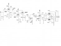
Cap is good - shows 200 ohm common cathode resistor (schematic says 250,should be 200)
Also swapped .47uf Coupling caps, same thing...
Also swapped .47uf Coupling caps, same thing...
Check the cathode voltage. If it is unusually high then the coupling caps are leaky or the valve is gassy. If it is unusually low then the cathode decoupler is failing when voltage gets across it - an ohmmeter check is not sufficient.
Last thing: if it uses a valve rectifier maybe this has very low emission?
Last thing: if it uses a valve rectifier maybe this has very low emission?
 Since this is a guitar amplifier discussion this thread has been relocated to Instruments & Amplifiers.
Cathode voltage 5.8v. Plate goes up to around 200v then drops to 96v
Cathode decouple cap removed - no difference
SS Rectifier - no tube rectifier....
Cathode decouple cap removed - no difference
SS Rectifier - no tube rectifier....
Last edited:
5.8V sounds rather low. Difficulty is that this could be a consequence of the supply rail drooping, or the cause of the droop.
Ha!!
Yes, it is the rail dropping. Just realized there is a high value resistor from original power supply circuit (10k 30w) and once changes to 680 ohm (50w Dale), the B+ returns to just under 400v.
Now to tackle the squeal at high volume (too much gain I'm thinking) and hum (need more B+ Filtering and raise heater AC ground)...
The phase inverter needs a coupling cap, grid leak and cathode resistor in order to bias it properly.
Don't run the NFB over tone and volume controls.
Make sure it is actually negative feedback. The squealing could be caused by positive feedback (reverse polarity on the OPT)
Don't run the NFB over tone and volume controls.
Make sure it is actually negative feedback. The squealing could be caused by positive feedback (reverse polarity on the OPT)
Last edited:
Thanks for the advice - it seems I have a fair bit of 120hz hum that I am pretty sure is power supply needing another RCRC filter - have only one RC now with 680 ohm, 270uf cap. Was going to add another few stages next...
Doesn't the 250 // 22n caps and 1M Drive pot function as the coupling cap and grid leak on phase inverter? I guess when gain and drive pots are tuned all the way down I have no grid leak....
A cathode resistor above the 22k with another 1M grid leak and coupling cap? I can try - any special values?
NFB point I can check. If reverse, would it squeal all the time, or just when high volume. Now it squeals only at high volume... Thinking this is OK..
Also now have 300v on 6L6GC plates and 23v / 62ma across 200 ohm cathode resistor, so 17 watts dissipation should ok for 6L6GC...
Things to do next -
- check NFB
- change all tone stack, input and output wires to shielded cables
- add another 300 ohm and 270uf filter, and maybe another
- separate 200 ohm cathode resistors on output tube, and see if bias currents from each are same
Last edited:
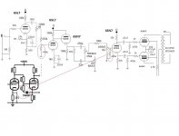
A revision on the schematic with added grid leaks and a little snippet from the Valve Wizard on Cathodyne modification that I am considering...
The Valve Wizard
The Valve Wizard
Attachments
Last edited:
Check grounding first. 270uF should be plenty.john65b said:Thanks for the advice - it seems I have a fair bit of 120hz hum that I am pretty sure is power supply needing another RCRC filter - have only one RC now with 680 ohm, 270uf cap. Was going to add another few stages next...
You're not there yet:
The rule of thumb of the valve wizard page says that the cathode voltage should be around 1/4th of the HT, and the grid (bias) voltage a little lower than that.
So if the HT is 300V, the cathode should be at 300/4= 75V.
The grid is perhaps 2V lower than that, so 73V.
In your design the grid is referenced to ground, so the cathodyne current will be close to cutoff.
Another thing you need to consider, is the NFB.
You can't wrap it around the whole preamp.
NFB straightens out non-linearities, so it will be fighting against the tone control.
Furthermore, including volume pots makes the amount of NFB dependent on the setting of these pots, again fighting the purpose of these pots.
First question: why do you want NFB?
Second: do you have enough gain that can be reduced by NFB? After the last pot there is only the cathodyne, which has less than unity gain.
Let's look again at the valve wizard page: the cathodyne stage is directly coupled to the preceding stage.
This puts the grid of the cathodyne at the required voltage and -since there is a stage that has actual gain- offers an opportunity to insert NFB (cathode of the stage before the cathodyne).
I hope you understand what I mean.
I'm posting from my phone, which is hard enough without drawing a picture 😉
Thanks to both of you - as soon s can get back home (out of town) I will look into the comments, but I do need both grid leaks?
Got it working now - as advised, I had a loose ground on input jack...also added another RC anyway. This thing is quieter than my Marshall SS amp.
One last problem is the bass pot - I turn it 1/100 up and all bass enters, rest of the 99% of pot does nothing...I think I am going to revisit that Tone stack and redo completely now that amp is working...
One last problem is the bass pot - I turn it 1/100 up and all bass enters, rest of the 99% of pot does nothing...I think I am going to revisit that Tone stack and redo completely now that amp is working...
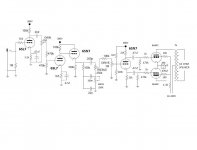
Finally fixed everything...attached is final amp. Nice....comments?
Attachments
Last edited:
The drive pot pulls down the DC on the grid of the phase inverter. Put a cap in between the wiper of the pot and the grid.
While you can provide the bias to the PI grid with this voltage divider, this will also put a positive voltage on the grid when the 6SN7 is still warming up (cathode still lower than the grid).
I think it's better to use a regular cathode resistor between the cathode and the 22k going to ground. The 220k then goes from the grid to the junction of the 22k and the cathode resistor.
- Status
- Not open for further replies.
- Home
- Live Sound
- Instruments and Amps
- Pin 4 Screen connection on 6L6GC PP Guitar amp drops B+