phase_accurate said:
Making them loud is even easier than generating the sound -that's why I spent less text on this part (but still sufficient IMO) in my post.
Regards
Charles
sorry, should have added ........on a 12v supply.
sorry, should have added ........on a 12v supply.
Sorry I should have added: Making them loud is easy for ANY supply voltage (anyone for 1.5 volts ???), if the relative bandwidth doesn't need to be very high.
Regards
Charles
Currently using a piezo on the function generator in sweep mode again to chase off the neighbours nosey cat.
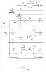
Looking at your latest schematic, I'm confused about the BDW93C (TIP142 & TIP147) & BDW94C (TIP142), which one is p-n-p & which one is n-p-n? Also, a single-supply would be nice. Thanks for this great job, it is almost at a point where I can duplicate it, given my non-existent skills.Gold_xyz said:New schematics III
This satisfies me more than the old version.
on Pspice it work very good.
An externally hosted image should be here but it was not working when we last tested it.
I also think that it can easily be converted to single supply...
ardo said:
Looking at your latest schematic, I'm confused about the BDW93C (TIP142 & TIP147) & BDW94C (TIP142), which one is p-n-p & which one is n-p-n? Also, a single-supply would be nice. Thanks for this great job, it is almost at a point where I can duplicate it, given my non-existent skills.
yep a single 12v supply with the same output would be VERY nice 🙂
Much simpler in my case if i can connect to a 12v battery, rather than runing cables.
this would eliminate the need for the level-shifting circuitry with which the designer is obviously struggling 😉I also think that it can easily be converted to single supply...
phase_accurate said:
Sorry I should have added: Making them loud is easy for ANY supply voltage (anyone for 1.5 volts ???), if the relative bandwidth doesn't need to be very high.
Regards
Charles
and i can build a coldfusion generator out of match sticks 😀
Play fair.................. you can't tell people you have the solution to there problems and then not tell them. Come on, if you know how its done and there are several people here without your experiance that would benifit from your help, post away...............Please.
Sorry for being a bit mean but I already hinted at possible solutions before.
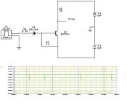
If you don't need a wide frequency range you can use the piezo's property of being a lossy capacitor to transform the input voltage to the desired level.
One possibility is a series tank circuit (left) and the other one is a parallel tank circuit with a tapped inductor (right). C-large is there to block DC and might not be needed in some cases (like bridge topologies). Another possibility, though very static in terms of output frequency would be the push-pull oscillator that I once posted within another thread.
Regards
Charles
Attachments
Graham Maynard said:Only there as an example !
Puts 24V square across the piezo without transformer.
I had one with three Motorola piezos and LM3900 warble driving a capacitor firing transistor npnp arrangement and step-up transformer (pcb about 1 x1 x2 inches) each but can't find the circuit I developed.
The beats were unbearable.
Was being designed as an airport bird scarer, one box could scare birds up to 1/2 mile.
Motorolas very directional at hf, thus if aimed into a neighbours garden will work over a very narrow range.
Any chance you managed to find the circuit? also can you remember what tranny you used.
cheers
I have just found this old thread.
somebody has really tried the project?
is it works.
Thank you
somebody has really tried the project?
is it works.
Thank you
I built the PCB for the attached schmetic of goldxyz with the power supply of +25 and -25 volts. It works fine up to 8kHz
and both transistor pairs remain cool but if you increase the frequency above 8kHz, the output waveform across the load(piezo or resistance) is no longer symmetrical. The negative portion of the output becomes longer than the positive. Also the NPN transistor extremly heats up at frequencies higher than 8kHz.
Still trying to get symmetrical output across the piezo with both cool transistors.
If you want to perminently deafen everything within a 2 mile radius then use the Eminence APT80 Tweeter, over 100dB sens, 5 - 25kHz freq and rated at a massive 600W RMS! 😀
Go gettem boy!
Go gettem boy!
ml342001 said:I built the PCB for the attached schmetic of goldxyz with the power supply of +25 and -25 volts. It works fine up to 8kHz
and both transistor pairs remain cool but if you increase the frequency above 8kHz, the output waveform across the load(piezo or resistance) is no longer symmetrical. The negative portion of the output becomes longer than the positive. Also the NPN transistor extremly heats up at frequencies higher than 8kHz.
Still trying to get symmetrical output across the piezo with both cool transistors.
thank you a lot, ml342001!
you have saved me to build a not good working project.
I'm trying to contact the original maker to see if it has improved his project.
Thanks again
The base current for the driving transistor 2N5551 should be adjusted as the frequency changes in order to have symmetrical half cycles across the load. With R1=3.6K the cyles are symmetrical but with 1K not.
Need to check the current gain bandwith product of 2N5551.
Need to check the current gain bandwith product of 2N5551.
phase_accurate said:Well, ultrasonics might be capable of both - attract and repel depending on signal type and level.
Regards
Charles
I think it attracts audiophiles too! ... with all that talk on analog source and berillium tweeters 😀
Any updates or new comments on the schematics in this thread? I need to "train" a neighbor's dog...😀
I'm thinking of experimenting with a Pyramid TW47 tweeter hooked to a 100W amp. The TW47 is rated at 125W RMS/250W peak, and has a 4.5 lb. (2kg) magnet. I hope to see any pest run far, far away.
If you have cats and tweeters that go high up, buy yourself a whale songs CD from Greenpeace or so - you'll have your home tigers sit in front of the speakers like they are bolted to the floor.
Haha, I love this ! 😀
Is it really true that cats love to listen to those CDs ?
If it is, please can you provide more details on the exact CDs they like ? 😛
- Home
- General Interest
- Everything Else
- Piezo Tweeter for Dogs