Hi all, I'm using The Realist Copperhead piezo pickup on my upright bass. I'm noticing the output seems to lack low frequencies. I discovered that this pickup requires its output be sent to an amp with 10Mohm input impedance. Most mainstream amps including mine are 1Mohm. Others in the community have reported impedance mismatch can produce this symptom.
I am looking to build this piezo buffer circuit. The designer has advised me: 'The usual input impedance of my circuit is about 4.8Mohm. It would be possible to increase the value of the 4.7M and 10M resistors if you need higher - mostly they are there to bleed off any DC offset.'
From this, I have determined I need to change the resistors marked below.
I'm hoping anyone here can tell me what resistor values I should use for R1, R2, R3 for an input impedance of 10Mohm.
The above circuit will cause exposion sounds if sensitivity is adjusted mid-performance.
Remove R1-R2 and both input caps and connect pickup straight to R3.
You can also lower 220k source resistor to, say, 47k or so, even replace the series output 10k by a 1k.
You don´t "need" attenuation, your pickup is not that loud.
If possible, build preamp in a small metal box, Altoid tins are fine, and mount it on your Bass.
If your amp is a tube amp with the usual 12AX7 triode input you can just replace the 1Meg Rg resistor on the input stage with a 10Meg.
On my home brew amp I have a 8M2 and 1M in series for this resistor with a switch labelled "piezo/normal" to short the 8M2 in the normal position.
This works well with piezo pickups ( I use it with a Fishman bridge pickup).
The 12AX7 datasheet will tell you that 10M is too large for Rg BUT the max Rg value of a tube on the data sheet is the max with the tube at maximum dissipation, you can safely go higher at reduced dissipation which is where your normal guitar amp input stage runs.
Cheers,
Ian
If your amp is a tube amp with the usual 12AX7 triode input you can just replace the 1Meg Rg resistor on the input stage with a 10Meg ....... I have a 8M2 and 1M in series for this resistor with a switch labelled "piezo/normal" to short the 8M2 in the normal position.
Not really, 10M is solidly into grid leak bias territory and will drop as much voltage on its own as the regular cathode resistor.
Shorting it will cause the mother of all thumps (we are talking an about 2V DC step at the input of a sensitive preamp).
True.The 12AX7 datasheet will tell you that 10M is too large for Rg
They "should" know, shouldn´t they?
Dissipation is irrelevant here, we are talking a Preamp tube.BUT the max Rg value of a tube on the data sheet is the max with the tube at maximum dissipation, you can safely go higher at reduced dissipation
Maybe you are confusing it with power tube maximum resistance grid to ground or bias point, which if too high (sometimes as low as 100k or 220k) can lead to thermal runaway.
PS: a regular FET or even better a FET input Op Amp does not have that problem.
Thanks for the great responses guys.
Yeah, I'm considering removing R1, R2 all together, but I will build it to suit whatever the pickup needs. The output is surprisingly hot for a passive pickup.
What is the benefit to changing the 220k and 10k?
Will removing caps influence reactance and change the sound in any way?
Is this referring to my original circuit or the one proposed by PRR?The above circuit will cause exposion sounds if sensitivity is adjusted mid-performance.
Remove R1-R2 and both input caps and connect pickup straight to R3.
You can also lower 220k source resistor to, say, 47k or so, even replace the series output 10k by a 1k.
Yeah, I'm considering removing R1, R2 all together, but I will build it to suit whatever the pickup needs. The output is surprisingly hot for a passive pickup.
What is the benefit to changing the 220k and 10k?
Will removing caps influence reactance and change the sound in any way?
I'm just playing through various compact transistor combos. This ridiculous instrument takes up enough stage space already!If your amp is a tube amp with the usual 12AX7 triode input you can just replace the 1Meg Rg resistor on the input stage with a 10Meg.
Mine will pop. Badly. You may not want to do it twice. I don't think you need to mess with it while the audience is in the house. I'd make it a solder-select.or the one proposed by PRR?
They are needlessly high and remember you will drive a longish cable after that, the values I suggest will make that easier, as in having a little more current available and lower effective output impedance.What is the benefit to changing the 220k and 10k?
Will removing caps influence reactance and change the sound in any way?
Current consumption will still be very low, any 9V alkaline will last a couple years, basically "shelf life".
And given the impedances at play, input capacitors are "transparent", so no audible difference.
They are needlessly high and remember you will drive a longish cable after that, the values I suggest will make that easier, as in having a little more current available and lower effective output impedance.
Current consumption will still be very low, any 9V alkaline will last a couple years, basically "shelf life".
And given the impedances at play, input capacitors are "transparent", so no audible difference.
Are the caps here really only for DC filtering or do they serve another purpose?
I can't seem to get hold of the 20pF specified by the designer. I can get 18 or 22pF. Will those values make a significant different to the circuit? Would too high or too low be a better choice?
Seems you can't edit posts on this board. I just realised the schematic has a 1pF cap, but the parts list on his website says 20pF. Now I'm even more confused!
You have 10 or 20 minutes after you post.Seems you can't edit posts on this board.
The 1pFd is obviously bogus (perhaps a scrap from an old revision). The 20pFd is not likely either. Leave this out.
Yes, such low values "do not do much"
A few pF across the input are generally used for RF protection, but typical value is 100pF or so.
In any case, a Piezo pickup is a capacitor, so it does the RF killing function on its own.
100pF across Pre input could protect it if Bass Pickup were unplugged, but in that case lots of hum will bethe problem.
You should use a shorting jack at the input, like all Guitar amps, so when nothing is plugged in, input is automatically shorted.
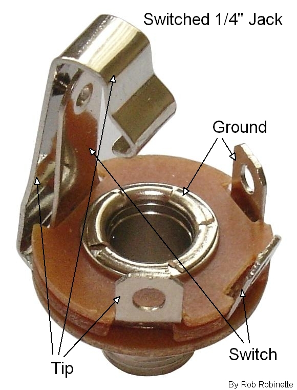
You short the "Switch" and the "ground" terminals with a piece of wire.
Notice Tip and Switch flexible terminals touch each other when nothing is plugged in so Tip - Switch - Ground terminals are joined together, so shorting preamp input to ground: no buzz - hum - only a little residual hiss. (nothing is perfect).
When you insert a plug, its head pushes the hook shaped terminal away from switch contact and input works as normal.
A few pF across the input are generally used for RF protection, but typical value is 100pF or so.
In any case, a Piezo pickup is a capacitor, so it does the RF killing function on its own.
100pF across Pre input could protect it if Bass Pickup were unplugged, but in that case lots of hum will bethe problem.
You should use a shorting jack at the input, like all Guitar amps, so when nothing is plugged in, input is automatically shorted.
You short the "Switch" and the "ground" terminals with a piece of wire.
Notice Tip and Switch flexible terminals touch each other when nothing is plugged in so Tip - Switch - Ground terminals are joined together, so shorting preamp input to ground: no buzz - hum - only a little residual hiss. (nothing is perfect).
When you insert a plug, its head pushes the hook shaped terminal away from switch contact and input works as normal.
I think I'll go with design as attenuation isn't important to me.
What arrangement would I need to make input impedance switchable between 5M and 10M?
Electrically?: switch a 10M resistor in parallel with the current 10M one
Sound wise? sound will practically not change, so not much justification.
Sound wise? sound will practically not change, so not much justification.
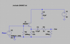
Here's a cleaned up circuit, stripped of the stuff you don't need.
A few points not mentioned yet:
1) If you add a 100pF cap across the input, it will reduce the output voltage from your piezo pickup. Unfortunately, the manufacturer of your Copperhead does not seem to provide the one specification we need: the actual capacitance of the pickup. Lacking this, I can't tell you exactly how much the output will be reduced by adding the 100pF cap.
2) Since your pickup is already "hot", try connecting a 4.7 nF (same as 4700 pF) capacitor between pickup output and ground; it will reduce the output signal, but it will also make the pickup compatible with a 1-megohm amplifier input impedance. If you still have enough signal level with the added cap, you don't need to build a preamp at all!
3) If adding a 4.7 nF cap kills signal too much, and you do build the preamp, it's important to add an additional resistor from output to ground (R4 in the schematic attached to this post). This will reduce thumps and bangs if you plug your preamp into the input of an amplifier that's already turned on.
(But be kind to your amp and speakers - plug in everything, keep the amp off, power up the preamp, wait a few seconds, then turn on the amp.)
4) I increased the preamps power supply filter cap to 47uF. The original value of 4.7uF is a bit stingy, and a 47uF cap is still very cheap. It needs to be rated for well over 9 volts. Doesn't matter if it's considerably more than 9V, i.e. a 25V part is perfectly fine.
5) This particular preamp (an FET source follower) can handle quite a big signal without distorting, so it shouldn't be bothered by the fact that your pickup is "hot".
-Gnobuddy
Attachments
Here's a cleaned up circuit, stripped of the stuff you don't need.
A few points not mentioned yet:
1) If you add a 100pF cap across the input, it will reduce the output voltage from your piezo pickup. Unfortunately, the manufacturer of your Copperhead does not seem to provide the one specification we need: the actual capacitance of the pickup. Lacking this, I can't tell you exactly how much the output will be reduced by adding the 100pF cap.
2) Since your pickup is already "hot", try connecting a 4.7 nF (same as 4700 pF) capacitor between pickup output and ground; it will reduce the output signal, but it will also make the pickup compatible with a 1-megohm amplifier input impedance. If you still have enough signal level with the added cap, you don't need to build a preamp at all!
3) If adding a 4.7 nF cap kills signal too much, and you do build the preamp, it's important to add an additional resistor from output to ground (R4 in the schematic attached to this post). This will reduce thumps and bangs if you plug your preamp into the input of an amplifier that's already turned on.
(But be kind to your amp and speakers - plug in everything, keep the amp off, power up the preamp, wait a few seconds, then turn on the amp.)
4) I increased the preamps power supply filter cap to 47uF. The original value of 4.7uF is a bit stingy, and a 47uF cap is still very cheap. It needs to be rated for well over 9 volts. Doesn't matter if it's considerably more than 9V, i.e. a 25V part is perfectly fine.
5) This particular preamp (an FET source follower) can handle quite a big signal without distorting, so it shouldn't be bothered by the fact that your pickup is "hot".
-Gnobuddy
Wow, thank you so much for your time on this. Very much appreciated! I will incorporate your changes and test the results.
I should probably add: I've decided to go down a different route to how others are using this circuit because I don't want to mount additional equipment to my bass. This circuit will have a long cable (1.5-2m) from the pickup going to the input, then a short patch cable on the output to the amp. Does this difference in transmission line length require adjustments to the circuit, or would the difference be negligible?
Last edited:
That shouldn't need any changes to the circuit (coax cable typically has it's own capacitance of around 100 pF per metre, so you will be loading your pickup with roughly 100 pF from the cable)....a long cable (1.5-2m) from the pickup going to the input, then a short patch cable on the output to the amp.
In general, a long cable at a very high-impedance point in the circuit (i.e. from piezo pickup to preamp) is going to be more prone to picking up hum, buzz, and other electrical interference. The only way to be sure if it's a problem or not, is to try it and see!
Bridget Kearney of Lake Street Dive is probably my favourite upright bass player:
-Gnobuddy
That shouldn't need any changes to the circuit (coax cable typically has it's own capacitance of around 100 pF per metre, so you will be loading your pickup with roughly 100 pF from the cable).
In general, a long cable at a very high-impedance point in the circuit (i.e. from piezo pickup to preamp) is going to be more prone to picking up hum, buzz, and other electrical interference. The only way to be sure if it's a problem or not, is to try it and see!
Bridget Kearney of Lake Street Dive is probably my favourite upright bass player:
-Gnobuddy
Would this mean the low impedance line between the circuit and amp is less prone to EMI? Maybe I'll have to live with strapping more stuff to the bass.
Awesome band! I actually performed that version/that tune previously.
In general, yes...this is one of the reasons why preamps are designed to have low output impedance. Interference has a harder time sneaking in.Would this mean the low impedance line between the circuit and amp is less prone to EMI?
Maybe try and see how it goes with the longer preamp-to-piezo cable first? Perhaps hum / EMI will be low enough not to be an issue.Maybe I'll have to live with strapping more stuff to the bass.
If you perform in multiple venues, one thing to watch out for (which I'm sure you already know about) is that the amount of EMI will vary, depending on the location and type of electrical / electronic devices in your vicinity.
Incidentally, if padding the piezo output with a 4.7 nF cap doesn't kill too much signal, it will not only make your piezo compatible with a 1M input impedance, it will also reduce the tendency to pick up EMI in the process.
Very cool!Awesome band! I actually performed that version/that tune previously.
I know Rachael Price tends to be the one who gets noticed (deservedly, she's an amazing singer). But when I first heard Lake Street Dive, it was the rhythm section that grabbed my attention. Kearney and Calabrese' playing was so incredibly tight, locked in like two people with one shared heart beat, and together they made such a distinctive sound, in our era of sampled drum loops, and generic-sounding electric bass players who rarely venture beyond roots and fifths.
My hat is off to anyone who can play that most cumbersome of instruments, the upright bass, and actually produce something that sounds like music from it. 🙂
-Gnobuddy
- Home
- Live Sound
- Instruments and Amps
- Piezo Buffer Upright Bass