Hi,
I've been looking at the type of dampers shown below, but can quite get over the fact that the tube sockets are going to be a good 6mm+ recessed below the chassis plate. I'd love to see some socket damper solutions fully installed to get an idea of the final look. Much appreciated!
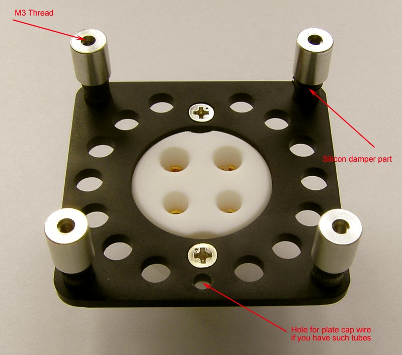
I've been looking at the type of dampers shown below, but can quite get over the fact that the tube sockets are going to be a good 6mm+ recessed below the chassis plate. I'd love to see some socket damper solutions fully installed to get an idea of the final look. Much appreciated!
How about the method Thomas Mayer uses?
I have copied them, buying the dampers and blocks separately.
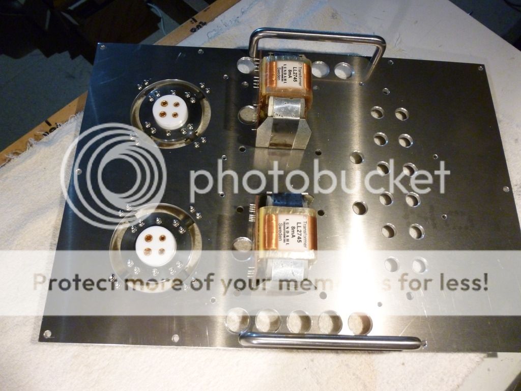
I have copied them, buying the dampers and blocks separately.
An externally hosted image should be here but it was not working when we last tested it.
Yes, jacmusic actually provides those as well with the mounts.
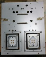
I found a pic of these things installed, and aesthetically, I think it doesn't look too bad:


I have what looks just like those from Michael Percy, EAR Isoloss sandwich mounts, $4 for 4-40 thread. I've used them for mounting circuit boards but have always been afraid to try them on tube sockets thinking they wouldn't take inserting and removing the tubes more than a few times.
Are you using that microphonic tubes? Normally decoupling the power transformer is adequate, I thought.
Yes, WE 101Ds. They're very microphonic. I'm considering, before I get too far along, removing a bit more rubber from the gap between the chassis and the socket mounting plate. I have already taken about 1/2" from each corner to provide more flexibility.
Raymond
Raymond
And I will be using type 26s, which are notorious for microphony.Are you using that microphonic tubes? Normally decoupling the power transformer is adequate, I thought.
Do the makers provide basic info on the damper such as self resonant frequency with a typical tube, and the Q at resonance, or is it all about good looks?
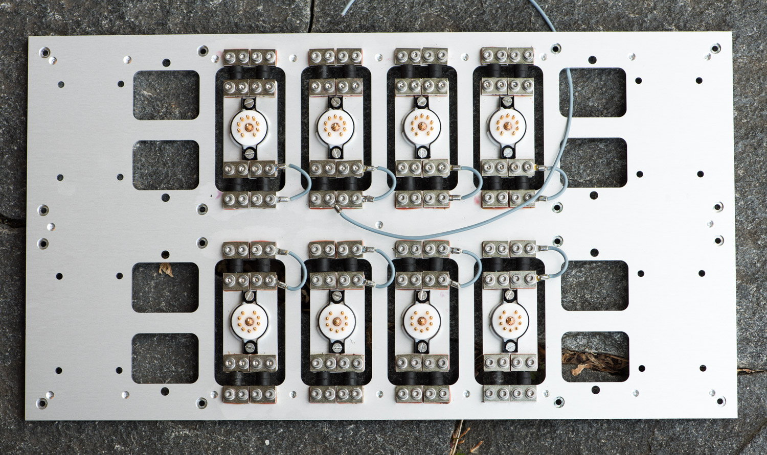
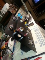
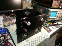
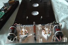
Here is an idea many you could try using mostly off the shelf parts. The springs are Latrax #7666 with a rate of .314 - these are used in RC car suspensions. The rest of the hardware is 10-24 threaded standoffs, and screws. Mass of the sub chassis is about 1kg, there is a step machined into the mounting holes to receive the springs - self centers nicely. Resonant frequency seems to be in the range of a couple of Hz, no idea of Q and no plans to measure it unless there is a problem.
Dave at Landfall gets credit for the idea.
Dave at Landfall gets credit for the idea.
Attachments
no idea of Q and no plans to measure it unless there is a problem.
The subtle catch22 scenario is when an amp exhibits some microphonics (ie. an easily objectionable sound) and then it is modified (either a tube swap or a socket vibration dampener of some type) and then no objectionable sound is observed - so problem solved - or is it?
Testing of microphonics, unlike testing of noise floor and distortion to levels of sub -100dB, is a rare occurrence, and may for many be masked behind the music.
Good point but very difficult to do a meaningful (controlled) test for most people. I can probably devise something to provide a consistent level of excitation to the chassis and do an FFT of the resulting signal.
Mine is intended primarily to deal with mechanical excitation of the chassis itself. I also don't expect the electro-static shields which are porous at audio frequencies to be much help at audio frequencies.
Edit: To your comment probably not resolved, but possibly at a sufficiently low level as to not constitute an audible nuisance. Does not mean eliminating it or pushing it further down would not be an audible improvement either IMO.
Yes its a tricky testing topic to make in to something tangible.
The system needing testing is the 'in situ' system with speakers and room and amplifier chassis placement/isolation. So its not a test to do on the workbench with resistive loads instead of speakers.
There also needs to be some duration to a test signal, in order to build up room modes and valve internal vibrations - or at least some characterisation of how brief a signal needs to be to avoid a microphonic generation. Not a peaceful test if using a high level tone or swept tone - and perhaps possibly damaging to some speakers.
At least modern spectrum analyser software can easily sit across the output signal and stray microphonic frequencies easily identified by eye, with wide discrimination above a noise floor and from amplified speaker signal and sundry related harmonics.
I've used them for mounting circuit boards but have always been afraid to try them on tube sockets thinking they wouldn't take inserting and removing the tubes more than a few times.
I bought similar items (male-female) from tme.eu (price about 90 -dollar- cent):
Transfer Multisort Elektronik - On-line Catalogue | 170 000 products offered.
I use these between 3mm top cover and subschassis (contains sockets, output capacitors etc) in my 10Y/801a preamp.
Attachments
Are you using that microphonic tubes? Normally decoupling the power transformer is adequate, I thought.
With simple grommets, or something else?
Here is an idea many you could try using mostly off the shelf parts. The springs are Latrax #7666 with a rate of .314 - these are used in RC car suspensions. The rest of the hardware is 10-24 threaded standoffs, and screws. Mass of the sub chassis is about 1kg, there is a step machined into the mounting holes to receive the springs - self centers nicely. Resonant frequency seems to be in the range of a couple of Hz, no idea of Q and no plans to measure it unless there is a problem.
Dave at Landfall gets credit for the idea.
Although, springs do a very good job of transmitting mechanical vibrations... Hmm.
Not quite that simple, think of them as a source of compliance between that which is vibrating and the item/mass you are trying to isolate.
With simple grommets, or something else?
Are such measures really necessary?
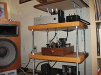
On my 76 pre-amp I used EAR SD-40, as I do in all builds, under the power transformer and simple sorbothane washers between the tube sockets and top plate. With a Broskie regulated DC filament supply and the above measures, it's absolutely quiet while residing too near the right speaker.
Attachments
The 76 is much less microphonic than some of the tubes being discussed here.
Certainly not overkill with the 26/12/01 in my experience. Others have reported the same for the 4P1L. My latest design uses the EML 20AM - from a microphonics perspective I am not yet sure what to expect.
Certainly not overkill with the 26/12/01 in my experience. Others have reported the same for the 4P1L. My latest design uses the EML 20AM - from a microphonics perspective I am not yet sure what to expect.
- Status
- Not open for further replies.
- Home
- Amplifiers
- Tubes / Valves
- Pictures of your socket dampers (shock mounts) installed!