My Sister didn't know anything about that...
...Anyway...It was a bit L O U D ...
...So I turned it down.
Didn't want my diode bridges cracked !
O U C H !
...Anyway...It was a bit L O U D ...
...So I turned it down.
Didn't want my diode bridges cracked !
O U C H !
No they aren't, just talking about capacitor's studsMmmm...
Interesting...
Is the RIFA PEH 200 a motor-run ?
I don't think they would allow a motor-run like that in the UK...
...could be wrong of course !
Cheers.
Si.

Cool.
Yeah...just talkin' about motor-runs.
Don't want to spread needless PANIC about exploding diodes...
...as was pointed out previously, 'motor-runs' ARE insulated...
...so your workshop air-compressor chassis; doesn't have 240 Volts A.C. on it.
Even the Health & Safety guys, 'sometimes', have a good idea or two.
Si.
Why all the chatter?
Where are the pictures of yout Pass DIY amplifiers?
Lol. I agree.
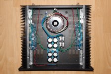
Here are some photos of my F5, to get the photo thread back on track... 🙂
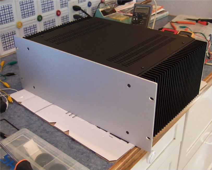
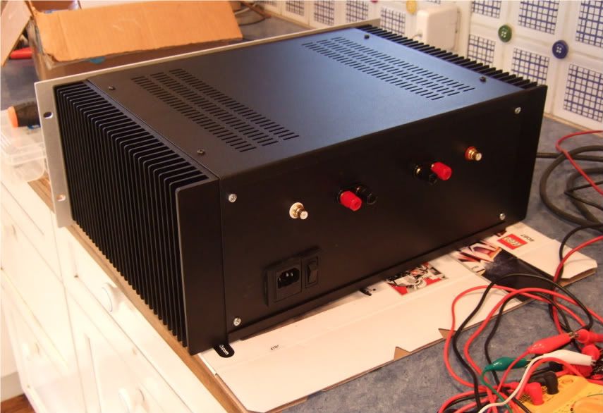
Here are pics of my F5 build. Pretty standard parts, nothing exotic. It is more than 2 years in the making, mainly due to not having any time to put it all together. In that time the F5T has been released, oh well may be I will have to build another.....
Attachments
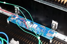

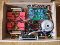
Please excuse my nubee knowledge level, but why are some power transistor positions not populated. That implies a lot more flexibility for this type of amp than I had suspected. Would be glad to read about the subject if someone points in the right direction.
Last edited:
Please excuse my nubee knowledge level, but why are some power transistor positions not populated. That implies a lot more flexibility for this type of amp than I had suspected. Would be glad to read about the subject if someone points in the right direction.
It's a dual purpose board.
Dual purpose meaning...........? That's a pretty broad phrase. Could you give some more detail.
Last edited:
Thanks 6L6!
bcmbob, I used cviller's boards which had the option of a few configurations. You can read about it in his blog. I believe the F5c boards available through the diyaudio store are similar.
http://www.diyaudio.com/forums/blogs/cviller/191-gb-f5-guide-pcb-version-2.html
I could have got close to F5T by using the extra output devices, adding diodes across the source resistors and upping the transformer secondary. But getting the standard version going took long enough and with 8 ohm speakers didn't think it was necessary.
sureshm, that's what I was after. I'll read that thread. I'm half way through a kit partially based on the F5 and didn't know if it was a universal option to use fewer transistors.
Thanks !
Thanks !
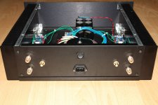
Bob - do you have the F5c board of the standard F5? They are 2 different units and on different pages at the store...
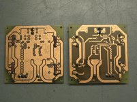
No, This is the one I showed you a few weeks ago. It is not a pure F5 amp but uses some of the the design elements. Had I known more at the time I would have bought something from the DIY store. JFET BJT Cascode....
Attachments

Last edited:
- Home
- Amplifiers
- Pass Labs
- Pictures of your diy Pass amplifier