B1 in an Onkyo 2nd attempt...
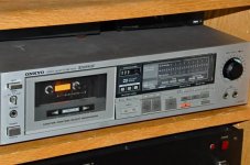
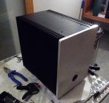
I built this B1 into an old Onkyo case. There is a Goldpoint stepped attenuator in the Recording Level location and the power switch is functional as well.
DSC_0099-1.JPG
I built this B1 into an old Onkyo case. There is a Goldpoint stepped attenuator in the Recording Level location and the power switch is functional as well.
DSC_0099-1.JPG
Attachments
I built this B1 into an old Onkyo case. There is a Goldpoint stepped attenuator in the Recording Level location and the power switch is functional as well.
DSC_0099-1.JPG[/QUOTE
I used a Sanyo case -- took contact cement and some aluminum flashing to veneer a new front to it -- this is a good technique for repurposing Japanese stuff. I use a Bessler roller knife to cut the veneer. Have also used black formica.
I didn't take any pics of the interior... maybe someday when I'm rearranging stuff again. Not much to see anyway... the standard board sourced from Pass mounted sideways down at the attenuator end. I hard wired from the Goldpoint (25K mini-V) to the board. Power comes in at the back on the opposite end and then through the power switch that was already mounted in the Onkyo. I feed it the 18V DC from an old Panasonic wall wart supply for a cordless phone... the Panasonic provides a spot on 18V with no ripple. I bypassed (jumped) the selector switch to simplify the signal path. It sounds marvelous.
just finished it then realized i never cleaned the pcb
An externally hosted image should be here but it was not working when we last tested it.
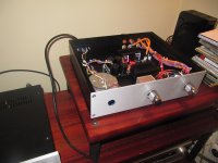
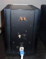
Wouldn't it be better to place the trafo a bit further away from the inputs? It seems to be enough clearance. I love the attenuator, by the way 😀 is it a Shallco?just finished it then realized i never cleaned the pcb
An externally hosted image should be here but it was not working when we last tested it.
Regards,
Member
Joined 2002
Wouldn't it be better to place the trafo a bit further away from the inputs? It seems to be enough clearance. I love the attenuator, by the way 😀 is it a Shallco?
Regards,
it's a medical grade shielded transformer, no need for space 🙂
Wouldn't it be better to place the trafo a bit further away from the inputs?
Regards,
i did those wires quick to test it. today i went and cleaned pcb and added a thick copper shield to both cables and rerouted them to make it look cleaner.
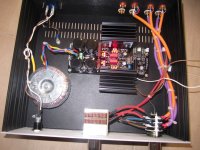
xformer in front
mains cable shielded , routed to switch on front plate , then to xformer
selector , attenuator , main pcb - everything near back plate
sel and att connected with extending shafts to front plate buttons
voila
boiled water
and most important - you can still do that
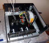
mains cable shielded , routed to switch on front plate , then to xformer
selector , attenuator , main pcb - everything near back plate
sel and att connected with extending shafts to front plate buttons
voila
boiled water
and most important - you can still do that
Amazing power supply and lovely construction.
One question:
Why the printed circuit board?
Okay... two questions...
Why not hard-wire this elegant circuit?
One question:
Why the printed circuit board?
Okay... two questions...
Why not hard-wire this elegant circuit?

Puffin - Beautiful! Congratulations on your completed build. 😀 😀 😀
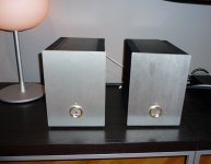
2 questions; What is the bit that looks like a display, and may we see a photo of the insides?
2 questions; What is the bit that looks like a display, and may we see a photo of the insides?
This pic was taken some time ago. I was intending to use a LiTe remote pre board with Alps pot. However the saound quality was nowhere near the lightspeed and so I removed it and have the source direct into the L/S and out to the B1. Really nice.
I am signed off by the doc at the mo and have been using my time to tidy up stuff that has been used in less than finished condition. The volume control is just to hide a hole😀
I am signed off by the doc at the mo and have been using my time to tidy up stuff that has been used in less than finished condition. The volume control is just to hide a hole😀
An externally hosted image should be here but it was not working when we last tested it.
Italian case (hifi2000) and possibly Italian granite. Very nice combo! 😉
Yes, please, display & inside!
edit: ops, we posted at the same time!
Yes, please, display & inside!
edit: ops, we posted at the same time!
Puffin - Beautiful! Congratulations on your completed build. 😀 😀 😀
2 questions; What is the bit that looks like a display, and may we see a photo of the insides?
The "display" window would have shown some LEDs as the LiTe has 4 inputs, but as that was abandoned, it is just for show. If I remove it I fear it will damage the front panel.

- Home
- Amplifiers
- Pass Labs
- Pictures of your diy Pass amplifier