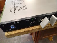
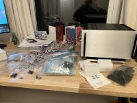
So, I had some leather left over from a college art project I did some 30+ years ago. I finally put it to some good use--embellishing the box for a H2 V2 preamp...

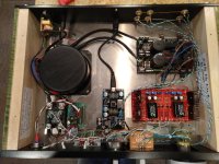
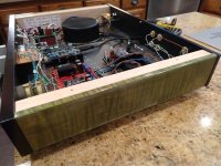
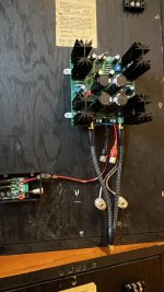
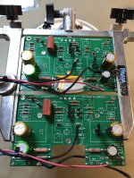
And here are the guts:

Yes, that's 4 inputs. Kinda overkill, but I had a 4-throw switch lying around....

Speaking of overkill...

Yeah, ball bearings for the volume knobs.
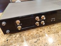
The faceplate & knobs are made from purpleheart & leather. The rest of the box is made from stainless steel & birch plywood. AB 25K volume pots. H2 V2 board and jfets from the diyAudio store. Not terribly satisfied with the volume pot shaft extensions; shouldn't be too hard to replace them somewhere down the road. Sounds great, as can be expected from a Nelson Pass design. Thank you, Nelson! Listening to a little Clark Terry now...
And here are the guts:
Yes, that's 4 inputs. Kinda overkill, but I had a 4-throw switch lying around....
Speaking of overkill...
Yeah, ball bearings for the volume knobs.
The faceplate & knobs are made from purpleheart & leather. The rest of the box is made from stainless steel & birch plywood. AB 25K volume pots. H2 V2 board and jfets from the diyAudio store. Not terribly satisfied with the volume pot shaft extensions; shouldn't be too hard to replace them somewhere down the road. Sounds great, as can be expected from a Nelson Pass design. Thank you, Nelson! Listening to a little Clark Terry now...

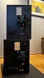
BA3 Front End......
Curly maple stained with aniline dye and lacquered
Panel/panel lettering is rattle can laquer and stencils made on a vinyl cutter.......letters are white lacquer on black lacquer
3 inputs: Bluetooth ($2 Ebay PCB), digital/USB (Ebay DAC), and Line in
Salas Shunt Reg Supply
works great.....
Curly maple stained with aniline dye and lacquered
Panel/panel lettering is rattle can laquer and stencils made on a vinyl cutter.......letters are white lacquer on black lacquer
3 inputs: Bluetooth ($2 Ebay PCB), digital/USB (Ebay DAC), and Line in
Salas Shunt Reg Supply
works great.....
Attachments


Last edited:
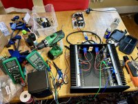
I cooked up a couple of F7-ish boards from @mareli . Everything went smoothly with SMPS for testing. Test speakers passed, so up it goes in the main system!
Big fun. Sounds great so far. I will need to add local cap banks and maybe output DC protection…
Big fun. Sounds great so far. I will need to add local cap banks and maybe output DC protection…
Attachments

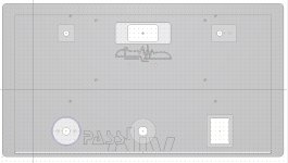
Thanks for the Files, Looks niceJust so that those interested can re-used and modify to their linking (bear in mind that i mentionned the NuTube preamp is a bit too high and the location for the potentiometer is a bit too low, post above) and to use the forum as an archive, here are the Schaeffer Front Panel Design files for front and back panels
Hope it can be useful to some.
Dieter
Attachments
I really like the external dual mono linear setup. Allows for more space in the various +/-24VDC class A amps. Once it's set in the system, it's a known quantity of quality. Swapping out the amp flavor of the month is easier. And lighter! The separate power supply can be a massive monster that rarely gets moved.
If you don't have a separate chassis ready, I'd say go ahead and build the M2X all together, rather than wait for more shipments. You can move the power supply out to another chassis when the time comes. Although that means you'll need another amp to go in place of the M2X while it is under surgery...
If you don't have a separate chassis ready, I'd say go ahead and build the M2X all together, rather than wait for more shipments. You can move the power supply out to another chassis when the time comes. Although that means you'll need another amp to go in place of the M2X while it is under surgery...
The beauty of where I'm at, I've got a pair of F4 clones in the system as my main amps. Wanted to try the M2x and various daughter boards but also have a bench amp for speaker building purposes. So, I could definitely take the time to wait on another chassis. In the least, like you pointed out, I'll have a bench supply for any other pre/amps to build.
Next steps are to do some layout measurements to see if a 2U mini-Dissipante will work.
Next steps are to do some layout measurements to see if a 2U mini-Dissipante will work.

4U for the mosfets, 2U for the PSU. Have to see if I can fit the transformers. Planning on mounting the rectifiers to the chassis heatsinks to save space.
Was surprised to see you using the 3U for the mosfets. How much heat are they sitting at?
Was surprised to see you using the 3U for the mosfets. How much heat are they sitting at?
Hello! My small adition to ACA builders - decided to connect wires using connectors - FASTON 2.8mm and inputs via PSH 3pins with the middle one removed (one channel is 4pin because I had only one 3pin). Wiring of the back panel is very simple for now - just for simple stereo amp.
To be honest I did not have much expectations (mainly max. power), but it sounds amazing and power is more than enough. I have a single-ended tube amp featuring 6C33C Russian power triodes and the sound is pretty similar. A class is very good, but damn that thing is hot 🙂
Thank You Mr. Nelson. P.S. I have to look to other Papa`s (hope I can call You that way) stuff 🙂
Likely not very interesting to anyone because I keep showing variations of the same thing, but my latest amplifier front end shenanigans looks like this. Didn't mess with boosted rails from an external supply or anything, but I have some bootstrapping going on to help with voltage swing. There's not too much "Stasis" left in it after all my massaging. So compared to the previous version at #6779, gain is now 14db (5X) with some new resistor values. R1=R3=16.2K... R2=R4=82.5K. Got rid of the input filter cap (C1) using the same trick as NP does on the new F5m, fat (enough) input resistor + combined gate capacitance of the jfets. Feedback cap is now a 3.3uF Panasonic polypropylene, thanks to the resistor change that keeps the cutoff low enough. The IPS get the same "lender" connection like the updated FE '22 has, and also the same 750 ohm in place of R5/P1. There's a 12 ohm degen resistor on the VAS emitter. Also was able to get rid of the lag compensation cap (miller). I had just a little overshoot with no compensation at all, 3.3pf in parallel with the feedback resistor (lead comp) seemed to be perfect. I didn't have a 3.3pf cap at the time so I have three 10pf caps (COG/NPO) in series instead, maybe even better VOLTCO in that case? It does see the full voltage swing right there, might be a good thing. The 20kHz square wave is perfect and the 100kHz signal is quite good also, probably the best I've had. I added a simple RC bootstrap on the positive rail, just to help the clipping behavior, since the negative rail still has the bootstrapped VAS (now a 1:1.5 ratio, 1.2K / 1.8K). I kept those values conservative, favoring a fast response rather than shooting for the lowest possible cutoff, while still being "low enough". So I have a 1.5K and 10uF series string there. SissySIT OS gets some of those cheap Dayton film and foils for coupling, just to try those out (no picture). Just one evening of listening so far, but a promising start..
Attachments

- Home
- Amplifiers
- Pass Labs
- Pictures of your diy Pass amplifier