With the completion of my B1K (still want to “upgrade” the volume control) my Pass stack is basically complete!
From top to bottom:
From top to bottom:
- B1K PSU and Pearl II PSU
- Pearl II
- B1K and Anthony Gallo Subwoofer Amplifier
- F6
Attachments


Hello out there,
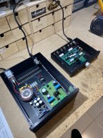
it took a long time till I gave the little H2-generator a 'house'. It had to live on a wooden board
for a few months and had to make some nice music...
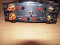
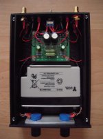
Battery-driven or from PSU (switchable). External measuring points (TP1/TP2) for easy access.
Cheers
and happy Easter!
Dirk 🐇🥚
it took a long time till I gave the little H2-generator a 'house'. It had to live on a wooden board
for a few months and had to make some nice music...
Battery-driven or from PSU (switchable). External measuring points (TP1/TP2) for easy access.
Cheers
and happy Easter!
Dirk 🐇🥚
Attachments


Dirk:
Very cute! How much time is it spending in your system, how does it sound (with battery vs. brick) and what preamp does it displace?
Regards,
Scott
Very cute! How much time is it spending in your system, how does it sound (with battery vs. brick) and what preamp does it displace?
Regards,
Scott
Hello Scott,
the H2-generator is in my case most often between a source and the preamp. I used it most often with
the B1 NUTUBE-pre, Waynes - Line - Stage and the ACP+.
For me this is a 'tool' to play with the soundcharacter. Not always to the better - but most often.
A simple Jfet in the signal-chain and its effects. I don't use it as a standalone-preamp.
As a comparison: it is a little bit like playing with a recipe that has been cooked by yourself many times
and you add some more salt or sugar.
The difference between battery-drive and a good solid PSU is for me not audible. Perhaps it is the noise.
This is why I use a battery-driven MC-phono-preamp.
Cheers
Dirk
dam1021 r2r DAC powered from and buffered by a DCB1
https://www.diyaudio.com/community/threads/soekris-dac-implementations.267948/post-4569955
into BA3 preamp with BiB shuntregs
https://www.diyaudio.com/community/threads/the-ba-3-as-preamp-build-guide.258022/post-6997846
into a diy F4 with a single pair of FQA12P20 and FQA19N20C outputs, initially built for headphones, but works great with 91dB speakers
https://www.diyaudio.com/community/...ing-the-pass-f4-amplifier.234355/post-6281443
Attachments


1) Thanks @myleftear. I am starting to consider building an M2x (started to order components,... might take a while to get everything), and i would have gone with Mini Dissipante 330 wide external 250mm internal due to space constraints in the rack/space i have. Now, i am .... slightly reconsidering the future box! (and location of the amp). I would go with transformer inside, bridget rectifiers & banks of cap.
From your pictures (very helpful!), it will be (very) tight also.
I will be careful to "prototype" on a board with the future case's constraints, to later see how i would go.
2) If you can tell how is the heat dissipation in this enclosure i would be very interested.
Have a nice day
Lolo6990, sorry your reply slipped through my filter!
In my minidissipante 4U (with the F4 in it), it is getting quite warm—chassis-temperature 45°C with 18° room temp, the amp bias set at 250mV (I believe).
I have to say that I haven’t yet looked into the chassis re:heat dissipation—I don‘t know how much heat the caps in the middle of the box are taking. But since the HS aren’t @&#*-hot and the ventilation is guaranteed, I‘m not worried!
Regarding space: i built the F4 with one huge 400VA transformer and huge capacitors… (ok, they’re big not huge) otoh, in old soul, there’s a true dual mono psu, 2x200vA and more reasonable capacitors (and no softstart etc, and it snugly fits in a minidissipante 3U… (heat-dissipation being much less critical!) here it is BTW: https://www.diyaudio.com/community/threads/old-soul.370744/page-26#post-6934802
A fearless builder (getzoff or similar) has his F4 in a 3U 300 afaik!
Last edited:
@myleftear , thanks for the feedback. It means i have to at least to 4U minidissipante and i will work out some equivalences between heatsinks given your build and the HS degreesC/Watt specs. Thanks againLolo6990, sorry your reply slipped through my filter!
In my minidissipante 4U (with the F4 in it), it is getting quite warm—chassis-temperature 45°C with 18° room temp, the amp bias set at 250mV (I believe).
I have to say that I haven’t yet looked into the chassis re:heat dissipation—I don‘t know how much heat the caps in the middle of the box are taking. But since the HS aren’t @&#*-hot and the ventilation is guaranteed, I‘m not worried!
Regarding space: i built the F4 with one huge 400VA transformer and huge capacitors… (ok, they’re big not huge) otoh, in old soul, there’s a true dual mono psu, 2x200vA and more reasonable capacitors (and no softstart etc, and it snugly fits in a minidissipante 3U… (heat-dissipation being much less critical!) here it is BTW: https://www.diyaudio.com/community/threads/old-soul.370744/page-26#post-6934802
A fearless builder (getzoff or similar) has his F4 in a 3U 300 afaik!
1 channel of an F6 in a 4U mini-Dissipante chassis with the diyAudio PSU board (incl. diode section). 500VA Antek transformer (overkill). Adding the 2nd channel in the next couple of weeks. Mounting the transformer vertically helped out quite a bit. I mounted the PSU board on some 30mm standoffs so I could tuck the thermistors and safety cap underneath. Tight but manageable.

Same 4U mini-Dissipante chassis with a smaller Hammond 220VA transformer and bridge blocks (intended for monoblock operation only).

Running only one channel, heat is not anywhere near an issue. The sink runs cool enough biased at 600mV I can leave my hand on it indefinitely. I've been considering cranking the bias a little more but I know the thermal load will change in adding the other channel.
Same 4U mini-Dissipante chassis with a smaller Hammond 220VA transformer and bridge blocks (intended for monoblock operation only).
Running only one channel, heat is not anywhere near an issue. The sink runs cool enough biased at 600mV I can leave my hand on it indefinitely. I've been considering cranking the bias a little more but I know the thermal load will change in adding the other channel.
Last edited:
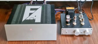

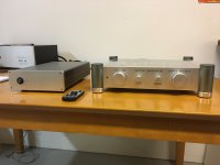
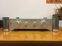
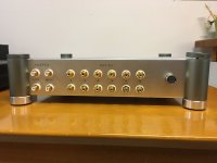
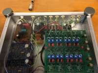
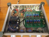
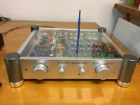
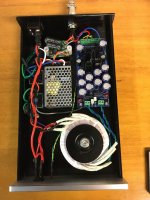
Here is my completed 6-24 active crossover in an integrated line stage. BA2018 line stage with Salas I-select input with Academy Audio VCU Muse volume control. The power supply is remote with a VRDN set to +18 -18vdc and a Meanwell hospital grade 24v SMPS with an SMPS filter in the power supply housing and another under the 6-24 PCB. Both power supplies have voltage adjustments, which I set under load. There is a +15 -15vdc regulator for the I-select, VCU and Mute relay. The 6-24 has 24 position 50K pots for low and high level, it uses 2SK170BL JFETs for the buffers. I used 6 matched pairs where the matching is left and right channels. I raised the 6-24 PCB and made a clear plexiglass cover with holes for the 6-24 adjusting pots.
Attachments

I wish I could say I'm close, I'm not. I'm in the process of building the SLOB speakers, which means just as I get done with the Lowthers, I'll have to start over again. My wife has better hearing than I do, so I rely on her opinion, and she is not always available to help.
I will photograph and measure the pots position so I can return to the settings when I swap speakers.
I will photograph and measure the pots position so I can return to the settings when I swap speakers.
I like the ex-inverter heatsinks - I have a couple of those, which I'm about to use for an Aleph build. 🙂This nightshift ends here...
Some work left.
Good night!
Dirk 😴
Not the easiest of tasks. I am using REW, and my ears. I guess at some point you have to state “good enough” because there are so many (too many) variables. As NP says, “it’s not dialysis“.I wish I could say I'm close, I'm not. I'm in the process of building the SLOB speakers, which means just as I get done with the Lowthers, I'll have to start over again. My wife has better hearing than I do, so I rely on her opinion, and she is not always available to help.
I will photograph and measure the pots position so I can return to the settings when I swap speakers.
My new Biamp 6x24 Xover is finished and playing fantastically in my kitchen. The enclosure stands side by side with a ACA mini. It is a FAST 2.1 System, the Bass driven by a 100W T-Amp.


Driving open baffles fullrange speakers (Diatone P610 clones). Xover 120 Hz / 24 dB

Driving open baffles fullrange speakers (Diatone P610 clones). Xover 120 Hz / 24 dB
Last edited:


- Home
- Amplifiers
- Pass Labs
- Pictures of your diy Pass amplifier