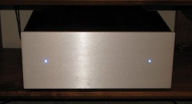
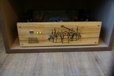
F5 diy clone, one of my builds
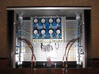
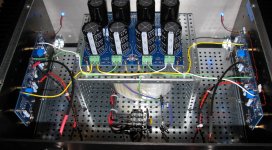
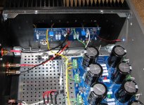
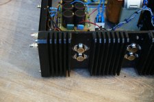
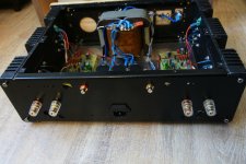
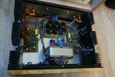
I have built or am building 5 of the First Watt / diyAudio clones and thought I would show one of the variations of power supply positioning / wiring I have found to be very quiet. PS board stacked on top of the Antek shielded 300VA power transformer, using Vishay 30A bridge rectifiers and 60,000 uf capacitance per rail. Have about 15mm of clearance for the top plate of the chassis in this arrangement. Very low self noise, I have to have my ear to my full range speakers to hear any noise from the amp.
Thanks, Papa, and all the diyAudio community for access to these great projects and amps!
Attachments
Beautiful work!
I have a deepness doubt: In general further a WAF decision, we are in general all DIY builders.
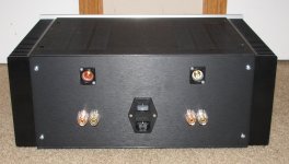
One in more some in less, My question related is: Why not put the in, and the output connector in the front of the devices that we make?
Best Regards to gentlemen
I have a deepness doubt: In general further a WAF decision, we are in general all DIY builders.
One in more some in less, My question related is: Why not put the in, and the output connector in the front of the devices that we make?
Best Regards to gentlemen
I'm away so can't post pictures but I put I/O in the front panel and power in the rear panel. For me it makes much easier to switch between amps.
Best
Bob
Best
Bob
I have often wondered why we allow the other half to demand that I/O are in the most inaccessible locations?.............. I put I/O in the front panel and power in the rear panel. For me it makes much easier to switch between amps............
Even us single men follow the mainstream.
Time we stood up for our right to make our own decisions !
But who would cook the dinner while we put our feet up and listen to the music?
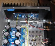
I have built or am building 5 of the First Watt / diyAudio clones and thought I would show one of the variations of power supply positioning / wiring I have found to be very quiet. PS board stacked on top of the Antek shielded 300VA power transformer, using Vishay 30A bridge rectifiers and 60,000 uf capacitance per rail. Have about 15mm of clearance for the top plate of the chassis in this arrangement. Very low self noise, I have to have my ear to my full range speakers to hear any noise from the amp.
Thanks, Papa, and all the diyAudio community for access to these great projects and amps!
hahaa, looks like old Meccano toys.🙂 Very nicely done! The perforated steel will surely dampen some of the electromagnetic fields.
Nice build.
I have often wondered why we allow the other half to demand that I/O are in the most inaccessible locations?
Even us single men follow the mainstream.
Time we stood up for our right to make our own decisions !
But who would cook the dinner while we put our feet up and listen to the music?
Except that even I don't like all those interconnects dangling out in the open, and in the way of wandering toddlers, cats, dogs, etc. etc.
I/O
Front I/O trending here, after two years use, I have put the on the front panel (mono's). They are soon to be moved on, I think front I/O offers wider appeal.
Front I/O trending here, after two years use, I have put the on the front panel (mono's). They are soon to be moved on, I think front I/O offers wider appeal.
I hear I/O in the front are trending?
It's quite handy, as is a mix of cinch and BNC.
looks like it not just my sisters telling me to become more "trendy" !Front I/O trending here, after two years use, I have put the on the front panel (mono's). They are soon to be moved on, I think front I/O offers wider appeal.
I'm away so can't post pictures but I put I/O in the front panel and power in the rear panel. For me it makes much easier to switch between amps.
Best
Bob
I put everything on the rear panel, but I ended up placing the amp frontside back for the same reason as yours. It's great, but a mistake I did was I put LED below the connectors, and I can't see it enymore after all the cables are connected...
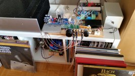
Finally got my B1/ironpre autoformer working. The boards and components been sitting in my storeroom for more than 5 years. Just found the time to complete it.


Many thanks to Nelson for the design, and zen mod for the autoformer idea. Appreciate also those in the forum that has helped to get this working 🙂
It is actually very very quiet. Complete silence at full volume going through my F6 and Harbeths. To be honest, the sound was too bright at first, so I switched the input caps from the epcos PP to Auricaps. Much better. It is still a bit bright compared to my Arcam FMJ pre out, but i take it as the 'character' of the preamp. It is getting better as I am running it in.
Sent from my iPad using Tapatalk
Last edited:
Have you checked/measured to see if the output is ringing when presented with fast transients?the sound was too bright
I have some of those transformers as I said.
I only have a Hanec 6022 be oscilloscope connected to a laptop so I can not state absolutes.
When fed the square wave generated by the scope the transformers did show some ringing.
As i only have limited equipment I am not sure that the effect was real.
Needs someone with better gear / knowledge to have a look.
Have you checked/measured to see if the output is ringing when presented with fast transients?
I dont have an oscilloscope 🙁
To all those fellows with a tendency to swap out units in their system and want cable accessibility... the answer is a rack on wheels. Skids will do if you can't work out the wheel part. Those "miracle" furniture glides are great!
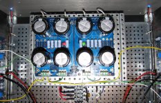
A source of inspiration for my latest AB100 Amplifier was Micro Article by Nelson Pass which began with the following words:
Since villagers armed with pitchforks and torches have begun camping
out my front door demanding a Class AB power amplifier
Technical details:
Bias 40mA per transistor - runs cool.
no turn on/off thumps.
PSU - +- 45V 30 000Uf in each rail.
indicator diode foe each rail.
Transistors - ztx450,550,MJ340/350, mj11016/15.
0,5 ohm emitter resistors and base stopper divided-100R on PCB and 100 on transistor base pin.
gain reduced approx to 27dB
I will measure later with scope and sound-card - now I am a little tired after amp hobby work 🙄
tnx Mr. Pass!
Attachments
- Home
- Amplifiers
- Pass Labs
- Pictures of your diy Pass amplifier