Hi,
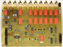
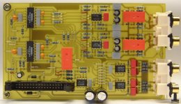
Thought that you'd be interested in seeing some pictures of my PGA2310-based preamp that I've been building. Full details are on my website - http://www.mhennessy.f9.co.uk/
I'm at the testing stage - so I haven't had a chance to critically listen to it yet. But, I'll hopefully be able to report back at the weekend...
🙂
Attachments


VERY nice looking work! Looking forward to the sonics report. Are you going to have the fancy front panel created also?
mlloyd1
mlloyd1
Member
Joined 2002
This is really good stuff, you have gone into great depth on your site it seems. I will be reading this shortly, lots of questions I've got are now answered. Wonderful.
the PCB´s have very clean lay out, Profi style.
It´s from what I understand a surround prosessor.
Good luck in finishing it.
I would like to see more pictures .
It´s from what I understand a surround prosessor.
Good luck in finishing it.
I would like to see more pictures .
Oh dear!
I promised you details of the sound quality at the weekend, but I haven't managed to try it in the hifi yet!
Unfortunately, I started playing with the software. This is the first time that I have had all 6 audio channels together with the relays, so I've been implementing all the main features I need to make it useful. So, in the last couple of days, I've added:
There's lot more little things like bugfixes and tweaks here and there. Trouble is, when I take a couple of hours to get 'into' the programming, I tend to go for days at a time while everything is fresh in my mind. I'm on a bit of a roll at the moment!
Still to come:
Thanks for everyones comments - I'm glad you liked the pictures!
mlloyd1 - A friend at work has a simple milling machine, so I'm hoping he will cut the display window and switch holes for me. Should be nice and accurate...
However, I've been so impressed by recent pictures from Peter Daniel and others that I'm considering ditching the 1U rack case and try custom-making something!
promitheous - did you find all the pictures you wanted on my website? If there's anything else you'd like to see, let me know!
Thanks again to all,
Mark
I promised you details of the sound quality at the weekend, but I haven't managed to try it in the hifi yet!
Unfortunately, I started playing with the software. This is the first time that I have had all 6 audio channels together with the relays, so I've been implementing all the main features I need to make it useful. So, in the last couple of days, I've added:
- Balance control: +/-8dB from left or right channels in 0.5dB steps.
- Surround level trims: +/-8dB in 0.5dB steps
- Rear Balance: +/-8dB, as normal balance...
- LFE L+R Mix option: As detailed on the webpage.
There's lot more little things like bugfixes and tweaks here and there. Trouble is, when I take a couple of hours to get 'into' the programming, I tend to go for days at a time while everything is fresh in my mind. I'm on a bit of a roll at the moment!
Still to come:
- Input trim: -1.5 to +14.dB in 0.5 dB steps (strange limits, but that is what's available after considering the balance and surround level controls).
- Save to EEPROM and power-fail routines: Still haven't tried writing to PIC EEPROM yet!
- Code for 12V triggers...
Thanks for everyones comments - I'm glad you liked the pictures!
mlloyd1 - A friend at work has a simple milling machine, so I'm hoping he will cut the display window and switch holes for me. Should be nice and accurate...
However, I've been so impressed by recent pictures from Peter Daniel and others that I'm considering ditching the 1U rack case and try custom-making something!
promitheous - did you find all the pictures you wanted on my website? If there's anything else you'd like to see, let me know!
Thanks again to all,
Mark
Mark,
Have some routines to have a pic (i'm using a 16f84) talking to a 24c02. Probably got them from the net somewhere. I'm using i2c for all communication, so only 2 lines are needed.
Drop me a mail if your interested. Maybe have a look at my site.
Like your PCB's, must have taken you a while to design.
Greetings,
Guido
Hi Guido,
Thanks for the offer. It's definately something I'd be interested in, although for this project I'm using the PIC's internal EEPROM (one day!)
I'd found your site just recently - very interesting. I like the idea of using a state-machine for the RC5 decode - not something I'd considered. How good is it? In terms of errors and responding to the wrong remotes, I mean. Mine is quite different to yours - it's not as clever - but it's proved to be quite reliable...
Before anyone asks, I'm not quite ready to release it to the world yet! It's still "my baby" 🙂
You're right, I spent ages on the PCBs. I quite enjoy it, I'm afraid! The main analogue PCB went through several drafts until I got something that looked nice, incorporated everything I needed, and felt electrically 'good'.
Spent all day on the software again, this time chasing silly little bugs 😕 The 80/20 rule definately applies here!
Listening tests soon, I promise!
Mark,
Where did you get your hands on the Noritake VFD, and how much did it cost? I've been trying to find a supplier for some time now...
Very nice job on the project! The PGA2310 looks like a real nice part... I'll be keeping my eye out for your listening results. 🙂
Cheers,
Where did you get your hands on the Noritake VFD, and how much did it cost? I've been trying to find a supplier for some time now...
Very nice job on the project! The PGA2310 looks like a real nice part... I'll be keeping my eye out for your listening results. 🙂
Cheers,
Hi hifiZen
I bought the display from Farnell for around 40 UK pounds. Check http://www.farnell.co.uk/
Shame the graphics displays are so expensive 🙁
I bought the display from Farnell for around 40 UK pounds. Check http://www.farnell.co.uk/
Shame the graphics displays are so expensive 🙁
Tell me about it... although 40 pounds isn't sooo bad for a VFD. If you want graphics display though, get ready to break the bank!
I've had decent luck finding surplus LCD screens for cheap, but for a top-notch project like this, you really do want to have a nice display. You have to be careful with VFDs though, as there seems to be a lot of quality variation amongst them. If you compare a Sony front panel display with something like a cheapo Apex unit, you'll see what I mean (Sony knows where to put it's money - aesthetics). Good VFDs are bright and crisp, and evenly lit across all the pixels. Bad VFDs are generally dimmer and you can see brightness gradients across the display (which also appear as sharpness gradients - yuk). I think Noritake is one of the best brands available however, so you shouldn't have any trouble with this display.
Can't wait to see some pics of the finished product! My vote: go for the custom case. You'll thank yourself later! 🙂
PS - Thanks for the info.
Yeah, go for a custom case. See what I meant good, old days. No displays then thou.😉
http://www.diyaudio.com/forums/showthread.php?s=&threadid=4572&pagenumber=1
http://www.diyaudio.com/forums/showthread.php?s=&threadid=4572&pagenumber=1
Mark,
The RC5 routine i am using works very well (i did not invent it, only migrated the code from 8051 to pic).
No problems at all with decoding RC5. I don't know of interference problems with non-RC5 remotes, i only have equipment with RC5 at this moment (TV,CD player, preamp).
I expect no problems though !
One thing i should mention. It assumes the pic is in sleepmode. When the code is received, the thing is woken up via the interrupt pin. Since it needs some time to start up properly, the first received RC5 frame is disgarded and it decodes the second coming in. Somebody using the code reported that his remote only sent one string when the key was pressed very shortly.
So then it wakes up, but does nothing until another keypress: it is waiting for the second frame, but will decode the first frame of another keypress.
I don't seem to have this problem, since i am using a (philips) programmable remote, which seems to always send out more than one frame when a key is pressed.
I started with an integrated SH505 or SH506 RC5 decoder with lense, but now i am using a receiver module from a TV (3047 or 3048 inside). This works MUCH better !!
Greetings,
Guido
Hi,
One other 'trick' if you have keys on the front of your case (i don't have any keys, only using the remote):
Get an old RC5 remote control and take it apart. Take the chip inside (no SMD is better, i guess) and put it in your own design!
You can take the output and connect it (somehow: OR port or transistor to pull the line low, depends on the receiver and the retrieved chip), to the connection between the RC5 receiver and the pic.
Hook up the keys on your front with the same code as sent by the remote and voila, you can read the keys on the front with no changes to your programming! The pic won't see the difference between front keys and remote. Also you don't need additional pins and interrupts.
Seen this done in my Meridian (202?) preamp..
The disadvantage is that the RC5 transmitter chip has it's own clock, which is then running all the time.. That is also the reason i did not put in a display, also has a clock which is switched on continuously.
Greetings again,
Guido
Peter Daniel: That was the thread that got me thinking about a custom-case! I'm very jealous of your aluminium skills - I'm sure I'll have lots of questions for you in the future 🙂
Guido: Thanks for the info. I decided againsts using sleep because, as you say, it does cause a lack of responsiveness. Philips remotes auto-repeat, but you do have to hold the key for a good half-second....
It's definately worth trying some non-Philips remotes - I found that some of them caused spurious codes to be generated. Something else that caused me trouble: florescent lighting. When I installed the recessed lighting in the workshop, my RC-5 code turned into a random number generator! Thankfully, all of these problems have been fixed now.
The RC5 code was one of my first bits of code that I wrote for the PIC. Now that I'm much more experienced with PIC programming, I intended to revisit the code to see if I can improve it. I will be thinking about your method very carefully. Thanks for your input 🙂
- Status
- Not open for further replies.
- Home
- Amplifiers
- Solid State
- Pictures of my almost-built preamp...