Seems like there is no need to normalise that intrinsic loopback performance for 1x. May be different for a 10x probe ? Not sure if FRA4 has an option to do a calibration adjustment (similar to eg. REW) to make a flat loopback with 10x probe, or for that matter with any external buffer amp etc.
Not sure how to interpret the gain (or phase) resolution to 6 digits in the FRA plot results table !
If you get the chance/interest, the ability of FRA4 to make practical measurements down to 1Hz (or lower) was a little uncertain from one or two posts over the years. I'm weighing up a 4224A, with the hope that FRA4 is capable of adequately plotting down to at least 1Hz.

Yup I can confirm that too. The capabilities available in FRA4 are determined by the scope connected to it, for example it is Flex Res aware and I can either let it pick or assign the bit depth I want to use.
This is a huge leap forward for me. Not that I had terrible scopes, but this brings a higher level of performance and some new features.
This is a huge leap forward for me. Not that I had terrible scopes, but this brings a higher level of performance and some new features.
What is the max steps per decade?Yes, FRA4Picoscope lets you go down to low frequencies. I just tried 0.1 Hz using my lowly 2204a and it worked fine. Just had to wait awhile!
jason
I just launched a 100,000/decade run and it started plugging away, but I am not willing to wait for it so killed it. If you are patient you can do as many points as you would practically want.
By the way, there is a 'calibrate' option under a menu but it doesn't do anything. But the app will export the data, so in principle you could use it to run both a 'calibration' run with just your scope (and perhaps any amplifier you add to the test setup), then do another run with the device under test. Then you can load the output files into some other software and make your own calibrated plots.
Edit: i have actually done this when measuring the frequency response of a output-filterless class-d amp that had differential outputs. I built a differential amp with lowpass filtering to include in the test setup. Pulled the resulting output files into Octave and made my own calibrated plots.
jason
Last edited:
I wondered about that, I assume the calibrate option will eventually work in some future update, even without, the errors are pretty small below 5MHz or so with the 5242D, it is likely that even at 10MHz the errors are acceptable if the response of the amplifier being measured is down more than 23dB or so. Exporting the data is an option so it would be possible to correct the error as you noted above. I think in most cases this will not be necessary in the usages I envision.
Further to Kevin's aim of this thread, I recently purchased a 4224A and have thoroughly enjoyed working through the global stability performance of about 4-5 valve amps now.
Mostly the concern is the HF end, and this tool with FRA4Picoscope software very quickly identifies resonance implications beyond the 96kHz that I was originally limited to (even though I sometimes went on a manual gain phase expedition with normal scope and sig gen). The affect of adding or subtracting compensation networks is quickly identified and provides confidence that expectations align with outcome.
One amp project involved a Williamson where I swapped in 6 output transformers that were advertised for Williamson application back in the 1940'50's, and could easily benchmark gain/phase for open-loop and 20dB closed loop feedback using the same amp and operating conditions. I'd suggest this was a lot quicker effort than done by Dixon in his 1953 NRL report on 10-odd different output transformers for Williamson use.
All of the recent 4-5 amps have been upgraded for unconditional stability (no load and a variety of capacitor only loads) using Patrick Turner's neat current feedback addition of a small inductor (circa 1uH). That inclusion can typically be tweaked for maximum flat gain bandwidth, with no final peaking, and often allowed other previous forms of feedback compensation to be removed, such as first stage step and feedback resistor parallel cap and any zobel networks on primary or secondary side of output transformer.
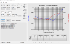
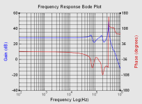
The most recent amp on the bench was a Williamson but with 807's running in pentode mode for the output stage. The output transformer was Partridge's WWFB and it was interesting to compare the HF response of the same OPT when triode driven compared to pentode driven. The first plot is for original Williamson triode mode (with 6L6GB) into rated resistive load and no forms of feedback compensation. The second plot is for 807 pentode mode under same conditions (feedback set to same 20dB level). Of interest is the more pronounced gain and phase disturbances due to OPT resonances that seemingly arise from the changed driving Ra of the output stage. The more onerous resonance out at 350kHz for pentode mode did require the use of a zobel on the OPT secondary (as well as current feedback inductor) to ensure unconditional stability, but HF bandwidth didn't suffer and remained out to 45kHz for -1dB.
That pentode mode Williamson also needed some modification at the low-frequency end as the existing coupling cap values were causing excess phase change and motorboating. It was a joy to confirm gain and phase down to well below the nominal 2Hz of the WWFB resonance, especially using Dave Gillespie's technique of substantially increasing one set of coupling cap values so that their corner affect was much lower than circa 2Hz.
For those that are 'into' restoration and/or design of valve amps, I can certainly recommend this path as a valuable adjunct to the modern day toolset of a soundcard and software.

Mostly the concern is the HF end, and this tool with FRA4Picoscope software very quickly identifies resonance implications beyond the 96kHz that I was originally limited to (even though I sometimes went on a manual gain phase expedition with normal scope and sig gen). The affect of adding or subtracting compensation networks is quickly identified and provides confidence that expectations align with outcome.
One amp project involved a Williamson where I swapped in 6 output transformers that were advertised for Williamson application back in the 1940'50's, and could easily benchmark gain/phase for open-loop and 20dB closed loop feedback using the same amp and operating conditions. I'd suggest this was a lot quicker effort than done by Dixon in his 1953 NRL report on 10-odd different output transformers for Williamson use.
All of the recent 4-5 amps have been upgraded for unconditional stability (no load and a variety of capacitor only loads) using Patrick Turner's neat current feedback addition of a small inductor (circa 1uH). That inclusion can typically be tweaked for maximum flat gain bandwidth, with no final peaking, and often allowed other previous forms of feedback compensation to be removed, such as first stage step and feedback resistor parallel cap and any zobel networks on primary or secondary side of output transformer.
The most recent amp on the bench was a Williamson but with 807's running in pentode mode for the output stage. The output transformer was Partridge's WWFB and it was interesting to compare the HF response of the same OPT when triode driven compared to pentode driven. The first plot is for original Williamson triode mode (with 6L6GB) into rated resistive load and no forms of feedback compensation. The second plot is for 807 pentode mode under same conditions (feedback set to same 20dB level). Of interest is the more pronounced gain and phase disturbances due to OPT resonances that seemingly arise from the changed driving Ra of the output stage. The more onerous resonance out at 350kHz for pentode mode did require the use of a zobel on the OPT secondary (as well as current feedback inductor) to ensure unconditional stability, but HF bandwidth didn't suffer and remained out to 45kHz for -1dB.
That pentode mode Williamson also needed some modification at the low-frequency end as the existing coupling cap values were causing excess phase change and motorboating. It was a joy to confirm gain and phase down to well below the nominal 2Hz of the WWFB resonance, especially using Dave Gillespie's technique of substantially increasing one set of coupling cap values so that their corner affect was much lower than circa 2Hz.
For those that are 'into' restoration and/or design of valve amps, I can certainly recommend this path as a valuable adjunct to the modern day toolset of a soundcard and software.
Attachments
Last edited:
- Home
- Design & Build
- Equipment & Tools
- Pico Scope 5242D/5243D - Any users here?