I have built a 10-channel power amp using LM3886's on Rod Elliott's PCB. I have a big shared power supply (1kVA transformer, 112000uF, etc).
I am getting between 13 and 50mV pk-pk of sharp spikes on the output (sounds like mains related buzz), co-timed with the charging spikes on the supply rails (about 350mV pk-pk sawtooth on 32V rails). Channels where the noise is below 20mV pk-pk are almost acceptable, but the one channel that is up at 50mV is a real problem.
Does anyone know where this pick-up is likely to be happening, and what I might be able to do to lessen its effect? Power supply rejection on the LM3886 is supposed to be 85 to 100dB - I am certainly not achieving this. Any clues as to why there could be such variability between channels? (doesn't correlate with position in chassis relative to power supply)
Many thanks
Jamie
Did you say 10 channels?
Did I miss something?
You're saying it's not power supply...at a guess, I'd look for a grounding/shielding problem. Be alert for cold solder joints.
Grey
EDIT:
Oh, yeah. Got a 'scope? Go hunting for oscillations. Chips are notorious for oscillating.
Did I miss something?
You're saying it's not power supply...at a guess, I'd look for a grounding/shielding problem. Be alert for cold solder joints.
Grey
EDIT:
Oh, yeah. Got a 'scope? Go hunting for oscillations. Chips are notorious for oscillating.
All the channels seem to be oscillating somehow.
Did you bypass the supply lines with caps close to each OPamp properly ?
Did you strictly obey to the "star ground law" ?
Did you keep a very tidy layout of all the wires ?
The difference between the channels relate probably more to the individual build quality of each amp. Power OPs are very sensitive for pcb layout (should not be a problem here), parts quality, not to forget the quality of the solder and the joints.
I have much better experiences with multi-channel amps using OPs by using partly separate PSUs (Shared transformer, one bridge and a pair of caps for each channel).
Try this, maybe it helps finding the faults:
Disconnect all channels but two and listen/measure again.
Put out one board and use it with a different PSU.
Klaus
Thanks for the rapid responses.
Yes, 10 channels. Wording may have been confusing - I'm using 5 of Rod's stereo PCB's, each sawn in half.
I'm using an analog 'scope which is how I found what I described above - digital 'scope wouldn't find it.
The circuit is slightly adapted from Rod's Project 19 suggestion to include more stabilization - I know that this can be counter-productive sometimes.
Positioning of decoupling on these boards isn't great, but I'm sure Rod would have changed it if it was a problem. For the 0.1u decouplers, I am using mylars because I had a pile of them lying around. I know people suggest ceramics - but I didn't think this would cause a problem. Also 220u electrolytics per rail on each module.
Wiring in a 10-channel amp is very difficult to keep tidy. The challenge of maintaining a low impedance to the power supply means heavy duty wiring which tends to go where it wants. The 10 modules are equally spaced around the power supply in a U, with all mains on the opposite side. Left on one side, right on other.
Grounding - I've put weeks of work into checking this. I now have ground-compensated outputs from my pre-amp eliminating inevitable loops in such a large system - didn't make a huge difference, maybe indicating my grounding was pretty good before. Implemented star-grounding as far as is possible with these PCB's. Shifted loudspeaker returns from star-point to amp modules just as an experiment - no difference. Connection from star to chassis/safety ground at one point via 100n/100R parallel network - no other 0V-safety ground connections in system.
I seem to have quite a bit of RF noise - maybe not surprising with the lid off, or maybe this is oscillation. Varies alot according to 'scope lead position.
Interested my problem might be oscillation - what are the symptoms of this? I'll do some experimenting today.
Again, many thanks
Jamie
... tried a 100n cap in parallel with each power supply rectifier diode to slow the peaks (Nelson Pass suggestion), but this has had no audible or measurable effect.
Also tried the worst module on its own. Noise is less bad, but still very noticeable.
Doug Self's site holds a few clues. Either provide separate decoupling returns to star (no longer much point in using Rod's boards if I do this), or try to minimize loops carrying half-rectified components to reduce induced pickup (these are probably extensive in my box - very difficult to resolve).
However, I can't help thinking these are palliatives, and my problem is pretty gross. Mind you, there's not much specific material out there on multi-channel amp design.
Jamie
I confess that I'm not clear on how all this is laid out, but you might try running the power for each channel through a low value resistor (22-47 ohms) into another cap (say, 100uF), thus:
main power supply->resistor->cap->individual channel
As a test of this idea, unhook nine of the ten channels from the power supply, and see if the one remaining channel runs cleanly. If it does, try the above.
Grey
main power supply->resistor->cap->individual channel
As a test of this idea, unhook nine of the ten channels from the power supply, and see if the one remaining channel runs cleanly. If it does, try the above.
Grey
Conventional linear power supply (www.linkwitzlab.com/xo_eq.htm - 3886pwr.gif). V+, V- and 0V from each module to the power supply (tee'd off smoothing caps).
Amp circuit is more like 3886amp.gif (see above) than Rod's Project 19 (no cap in the signal path, fitted stability components that Rod left out). Though I have included Rod's local 220u decouplers.
My pre-amp outputs are ground compensated (as per Doug Self's circuit) to avoid loop problems with so many channels. Shield connects to cold wire at amp module (soldered to PCB - no connectors) and this is subtracted from the signal at the pre-amp to remove any ground voltage difference. Moving to this from unbalanced made the problem better, but didn't fix it.
With only one power amp channel connected, if I terminate the input and use an external (bench) supply, the output is clean.
As soon as I connect my pre-amp (not powered), low level spikes appear (few mV). When I power up the pre-amp, they get much worse (~+12dB).
As I hook up other power amp channels, the spike amplitude increases, and I get more of them.
Taking Rsn / Csn out made no difference. Providing a dedicated return path for decouplers made no difference.
As I can still measure spikes with only one channel connected, I am not convinced that providing separate supplies for each channel will help.
Any clues as to how I determine if this is oscillation, pick-up or something else?
Amp circuit is more like 3886amp.gif (see above) than Rod's Project 19 (no cap in the signal path, fitted stability components that Rod left out). Though I have included Rod's local 220u decouplers.
An externally hosted image should be here but it was not working when we last tested it.
My pre-amp outputs are ground compensated (as per Doug Self's circuit) to avoid loop problems with so many channels. Shield connects to cold wire at amp module (soldered to PCB - no connectors) and this is subtracted from the signal at the pre-amp to remove any ground voltage difference. Moving to this from unbalanced made the problem better, but didn't fix it.
With only one power amp channel connected, if I terminate the input and use an external (bench) supply, the output is clean.
As soon as I connect my pre-amp (not powered), low level spikes appear (few mV). When I power up the pre-amp, they get much worse (~+12dB).
As I hook up other power amp channels, the spike amplitude increases, and I get more of them.
Taking Rsn / Csn out made no difference. Providing a dedicated return path for decouplers made no difference.
As I can still measure spikes with only one channel connected, I am not convinced that providing separate supplies for each channel will help.
Any clues as to how I determine if this is oscillation, pick-up or something else?
I find it suspicious that the amp begins to misbehave when the preamp is hooked up. Any chance of trying the amp (either one channel or more) with a different preamp? Incompatibilities between preamps and amps aren't common, but they do happen.
Grey
Grey
There are several possibilities here:
Grounding
Oscillation
Transformer field
I think the most probable is the transformer field
inducing noise into ground loops.
Take the transformer out of the chassis and hook
it up a couple feet away and see what happens.
Grounding
Oscillation
Transformer field
I think the most probable is the transformer field
inducing noise into ground loops.
Take the transformer out of the chassis and hook
it up a couple feet away and see what happens.
Nelson
Many thanks for the suggestions.
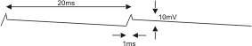
Attached is a drawing of the AC component of my +ve supply rail (-ve is mirror of this) loaded only by a 3k resistor (no amp modules). The peaks are slightly rounded.
This component grows, as expected, with load. I am worried about the spikes, or the rapid initial decay after the peak, as it is these spikes that seem to be getting though to my outputs. I would have expected to see a more regular sawtooth on the supply rails.
I have got 100n caps across each diode in the bridge.
On your point about the transformer, I didn't suspect this because I assumed that the spikes would be introduced by the bridge or the smoothing caps.
Is a waveform like this normal, or does it indicate a problem?
Many thanks
Jamie
Many thanks for the suggestions.
Attached is a drawing of the AC component of my +ve supply rail (-ve is mirror of this) loaded only by a 3k resistor (no amp modules). The peaks are slightly rounded.
This component grows, as expected, with load. I am worried about the spikes, or the rapid initial decay after the peak, as it is these spikes that seem to be getting though to my outputs. I would have expected to see a more regular sawtooth on the supply rails.
I have got 100n caps across each diode in the bridge.
On your point about the transformer, I didn't suspect this because I assumed that the spikes would be introduced by the bridge or the smoothing caps.
Is a waveform like this normal, or does it indicate a problem?
Many thanks
Jamie
Attachments
That's a typical waveform, but the amplitude is
much too high. You want it below a millivolt or
so at peak
much too high. You want it below a millivolt or
so at peak
After looking at the oscope trace you posted and running a simulation of the circuit you described it looks like the transformer/diodes/filter caps are generating a RF pulse at the time the diodes switch on to charge the cap. This is caused by the very high current required to charge a cap this large (over 200 amps for the first half cycle) and the transformers reactance to the change in current in the secondary winding. Your making the transformer ring at RF.
I would suggest that you use seperate diodes/ bridges and smaller filter caps for each amp module, 10000uf or so. Don't use super fast recovery diodes, use the slowest ones you can find that will handle the current. This should prevent the high current transient pulse and get rid of you noise.
I would suggest that you use seperate diodes/ bridges and smaller filter caps for each amp module, 10000uf or so. Don't use super fast recovery diodes, use the slowest ones you can find that will handle the current. This should prevent the high current transient pulse and get rid of you noise.
Thanks for the suggestions.
I tried some smaller caps (2x 4700uF instead of 2x 56000uF) just to see what difference this made. The sawtooth amplitude increased significantly (more or less in proportion to the difference in size of the caps as expected), but the spikes are still there! Again, this is with just a 3k resistor + LED as a load.
I really need to get a new soldering iron before trying Nelson's suggestion of moving the transformer outside the box, as the secondary center tap / cap center took 30 minutes to solder.
On this subject, are there any critical issues with connection points in the power supply? I know that the rails must be taken off the caps, not the rectifier, and that the 0V star should be tee'd off from the smoothing cap interconnection. This interconnection is soldered directly to the secondary center tap.
Having compared the performance of my supply to those in other amps I had lying around, I no longer think that the spikes on the rails are the direct cause of my buzz problem. In fact my new supply looks much better than the other ones.
One thing I did find was that the secondary center-tap solder connection was not at all good (it's just come loose) - I need to go and get a bigger soldering iron before finding out if this makes a difference. I can see that it might.
One thing I did find was that the secondary center-tap solder connection was not at all good (it's just come loose) - I need to go and get a bigger soldering iron before finding out if this makes a difference. I can see that it might.
if you have some large main caps going off via wires to the boards power rails which have smaller caps on the rails, try taking the smaller caps on the board out. Some times you can can get parasitics of caps charging each other backward and forwards, even though the cable is fairly thick
Thanks Helix, sounds interesting. I'll add this to the list of possibilities.
I have verified the rejection ratio of the amp modules by powering them from an inferior supply, which has spikes still, but much higher ripple. With a terminated input, outputs are silent (with ear pressed against directly driven speaker cone).
Put the pre-amp back in circuit, and much of the buzz returned.
The one thing I never checked was for the presence of spikes on the rails of the pre-amp (the scope won't read anything sensible on the line outputs of the pre-amp). Hey presto, little tiny spikes.
I then looked at the mains on the scope - what an unholy mess! Rubbish all over the place, with a consistent nasty spike in the first quadrant. Probably being coupled to the supply rails and signals.
So I sawed the pre-amp power supply in half (!!!), put the transformer a couple of meters away, and the amplitude of the buzz reduced to an acceptable level (barely audible 1 meter from speaker).
Hooking up my main power supply for the power amp again, more buzz returned, but at a lower level than it was originally. Next step is to follow Nelson's suggestion and move the power amp transformer and mains wiring out of the power amp chassis.
I guess an alternative might be to try a mains filter.
Since the noise doesn't appear until the preamp is connected, I see no alternative other than to conclude that is the source. Try connecting a .22uF cap across the secondry of the preamp's power transformer. Off of what voltages does the preamp run? Maybe consider also running the preamp off of voltage regulators which may buffer it from power line noise.
The pre-amp runs off +12-0--12V. It is a regulated Lambda supply, giving 1A per rail which I need (active filters).
The noise is also present when I run the power amp with its own supply (details above) and the inputs are terminated (i.e. no pre-amp). So I believe that mains pick-up is the culprit, and causing problems in both the pre- and power-amps.
So, as I see it, the solutions are either:
1) Remove mains from both boxes (already successful for pre-amp)
2) Filter the mains to get rid of the nasties that are being picked up.
Jamie
Maybe try a capacitor across the secondary of the power transformer to the amplifier also. Also, one thing I just thought of. I am not sure of how your set-up is configured, but I recall that problems can occur if the phasing of the mains power inputs to the components doesn't match up. In the past I recall having to turn plugs over in the wall outlets to stop hum. But that may be something else.
Since the noise doesn't appear until the preamp is connected, I see no alternative other than to conclude that is the source.
This is a very common mistake, the connection of the pre-amp to the input causes the noise to appear, but it isn't the source of it
- Status
- Not open for further replies.
- Home
- Amplifiers
- Solid State
- Pick-up of charging spikes