Ready for actual hybrid amp prototyping
I've got all the needed supplies breadboarded: +/- 180, -540, +/-56 (output rails) as well as the special filament & logic level supplies. Now, I'm ready to actually start building a test channel. For starters, since the mosfets are basically high power followers, I'll build just the compactron 'op amp' part of the amp to do initial measurements, & dc offset and stability analysis. Once that looks ballpark, I'll tack on a couple pairs of output mosfets and dial in the turn on & turn off circuits and, when all seems well, actually listen to some music through it.🙂
Btw, I've collected zero shocks so far on this project. I usually eventually zap myself once or twice on stuff like this, but am hoping to improve my record.

Do you need the PSU schematic also ?
Hi Morfeas,
Thanks for the schematic!
I won't be needing the PSU schematic...thanks.
Cheers,
Bas
I've been doing some testing & tweaking with the 6K11 input/driver circuit and am getting some promising results as well as ideas of how to improve it (raising the supply voltage slightly to stay more linear & out of feedback input grid current with large voltage swings, for one). The basic configuration is of the 2 high u sections as a diff amp with the non-inverting section driving the medium u section as a follower through a resistive divider chain.
The plate of the input triode (when considering this as a noninverting amp with loop feedback) is tied directly to the positive supply and the long tailed pair cathode resistor ties to a negative supply of the same voltage as the positive supply. The medium u section as a CF is also connected between the balanced plus and minus 200V supplies. I'm looking forward to hearing how all this sounds when I hook up power mosfets (pretty soon) because, although it does use loop feedback, it is around only one voltage gain stage (12ax7 section equivalent) and two followers in cascade (the medium u stage and the power mosfets) and AC loop feedback will only be around 6db. I expect to set the mosfet bias moderately high to help intrinsically linearize the output stage, btw.
One reason I'm doing it this way is to keep the total DC supply current path directly from the plus to the minus 200V supplies which helps maintain a low offset when using the whole as a part of a DC coupled amplifier and hopefully will maintain good tracking and offset control when the AC mains voltage changes.
Just recently, I returned the lower resistor of the divider chain to the - 200v supply rather than the -600v supply which may actually be helping to reduce offset drift even though I'm losing 1.5db of open loop gain this way. Over the last two days, after the circuit warms up for a few minutes, it has been stabilizing at 20mV DC offset or better. Of course, I don't expect long term offset to remain this good, but if I can get some confidence it will probably remain not too far from, say, 100mv or better for several months or longer between adjustments, that should be good enough. I can probably help maintain offset stability by choosing overrated resistors with good temperature stability for the input stage and divider. And, if all this doesn't work out quite as expected, I can work up a digital pot circuit with memory that can do auto offset correction triggered by either a button push or a built-in timing circuit.
I'm a bit surprised by the bandwidth of the circuit (sans mosfets). It has full power bandwidth at the -3db points to beyond 100khz and small signal response to 500khz or so. It looks like around 1% distortion at full power may be achievable with this design as a front end for a 150Wrms hybrid amplifier. The distortion is predominantly 2nd and 3rd order according to the scope spectrum analyzer I used.
Ooops. I just found out that the dc offset is rather sensitive to mains voltage variations. I rigged up a circuit to drop the AC input voltage by about 20%, and the DC offset went negative by 100mV. Now, I figure there's two possible contributing causes: either the drop in filament voltage is affecting the emissions of the tube sections differently, changing their plate resistance, transconductance, etc. and/or the circuit offset is simply sensitive to supply voltage variations. I'll isolate the former initially by running the filaments from a separate supply. If the problem disappears when I drop the supply rails then, all I have to do is design in a regulated DC supply for the filaments. If part or all the problem remains, I'll have to rejigger some part of the design itself. I have a suspicion what might be the cause in that case, although I should test before commenting further on that.
Well, it appears that both the filament voltage and the circuit topology affects dc offset stability. The good news is that a regulated filament supply and connecting the plate of the noninverting input triode to approximately half the positive supply voltage of the other connections largely accomplishes this, dropping the offset shift from 100mV to less than 20mV when going from 120VAC to 85VAC. However, my function generator died this weekend, and I'm hoping I can fix it so I can judge the effect of the circuit change on large signal handling. I may have to increase the supply rail voltages to maintain sufficient swing capability from the diff amp to drive the output stage with these changes.
You might want to consider a wheeze that regulated power supply designers used for stabilising against heater voltage variation. They would take a (thermionic) diode from the regulated HT to one input of the differential pair (plus resistor to ground, to form a potential divider). The idea was that increased LT made the diode conduct better, and this increased current could be used to offset the variations in the rest of the circuit. I imagine that a certain amount of experimentation with a variac and variable resistor would be required, but it might be cheaper than regulating the heater supplies...
An observation
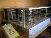
An observation; seems alot of these really nice projects are photographed on the floor. Does anyone use them on the floor?
An observation; seems alot of these really nice projects are photographed on the floor. Does anyone use them on the floor?

Bas Horneman said:Thanks...John,
Trying to advance little by little...I found aluminium..and I suppose all metals very unforgiving!!! Not fun working with if you don't have the tools...
Hi there........bit late responding to this.....for working in aluminium I nearly always use wood working tools to get a move-on......a rasp or a b astard file (yes joined up it's the right trade word)...standard fine files for ferrous clog up very quickly with ally. However with a rasp one needs to have the piece fixed in a vice and best work with gloves incase one slips.
richj
Hardi (or anyone else who knows),
In the Photo Gallery, Post #449, you can see a beautifully made tube amp. I am wondering where I can source feet like those?
I find chassis feet of new quality to be among the most ellusive of parts. Would greatly appreciate info from anyone in the know.
In the Photo Gallery, Post #449, you can see a beautifully made tube amp. I am wondering where I can source feet like those?
I find chassis feet of new quality to be among the most ellusive of parts. Would greatly appreciate info from anyone in the know.
I found a 5' piece of 2.25" bar stock in the scrap yard I used for knobs and feet. Cut it on a chop saw with alum cutting blade
http://www.crcpress.com/shopping_cart/products/product_detail.asp?sku=1345&parent_id=&pc=
Check this out, "Power Vacuum Tubes Handbook". This will mean tubes bigger than KT88 or 6L6. Its intended for radio transmitters, but still relevant for extreme audio.
****** cross posted on Audio Explorations
http://groups-beta.google.com/group/audioex_odds_ends/post?hl=en
Check this out, "Power Vacuum Tubes Handbook". This will mean tubes bigger than KT88 or 6L6. Its intended for radio transmitters, but still relevant for extreme audio.
****** cross posted on Audio Explorations
http://groups-beta.google.com/group/audioex_odds_ends/post?hl=en
Harman Kardon Trio A224
I have recently bought A224 amp, but it came with all the tubes removed. If someone could tell me as to how the tubes need to be placed, that'll be great
I have recently bought A224 amp, but it came with all the tubes removed. If someone could tell me as to how the tubes need to be placed, that'll be great
801/211 SET Design
This project has been started by me over a year ago.
Initially there were problems with transformers
No I am using discreet transformers for all the stages
The moot point is whether 801 can drive 211 in SET Mode
Where could I get the o/p transformer for the same
If someone could be give me the design, its possible for me to build one in Mumbai itself
richwalters said:To Johan Pot# About 15 yrs ago when I designed this amp I stylishly holed the top plate do this to stop it overheating. With wide envelope tubes like Kt88' and coke bottles this is necessary.
I found this now again; if I did not thank you then, I do so now. I have just posted views of my 100W stereo on Picture Gallery, though I imagine I did so somewhere before. Those are the original photos; I have since had to drill holes in form of a cross between the 6L6s (even though not wide envelopes), plus a little blower underneath. A multimeter with a temp. probe on a long lead broadened my horizons as to what temperatures existed where - rather an essential accessory.
I have since redesigned on a larger (area) chassis
 - strange what difference a little air flow can do. Temperature top of chassis (air) between 6L6s went from 68 to 35 degrees. Sort of funnel effect, also ventilates below chassis (chassis about 10mm off baseplate).
My father was planning to build an 807 based Williamson amp back in the early 1950s. He bought the tubes, which we still had many years later when I was a young boy. He bought the Heathkit 5881 based Williamson instead of rounding up all the other parts, and just held onto the 807s. I came across the amp pictured in the link below when I was in college, less tubes and picked it up. I think it is an earlier Heathkit 807 based Williamson, but I'm not positive. It has a Peerless output transformer, and I don't have the matching power supply, but I do have several power supplies that will work. The Heathkit my father built has an Acrosound output transformer.
http://baselaudiolabs.googlepages.com/Williamson3.JPG
I'm considering rebuilding this amp for use as a guitar amp for my son. Really, it would just be a basic rebuild, but I'm wondering if it has any historical value. It is triode mode only, as the transformer does not have UL taps.
Anyone have a match for it, might make a nice conversation piece set up in a small stereo system.
Pete B.
PB2 said:My father was planning to build an 807 based Williamson amp back in the early 1950s.
This reminds me of the huge amount of surplus www2 gear around during that period. At the time there wasn't an inch of sparetime boredom and a glance at the 1955 wireless world ad columns leaves one in no doubt. Names as Stern Clyne, RSC and hosts of other improvised amps were around. The non isolated AC/DC chassis radio's were quite the norm.
Nearly all the quitar amps around were pentode config and commonly worked into 15 ohm loads. A triode guitar amp would sound quite soft but play pleasant. I would be tempted to try with the NFB loop disconnected or very little global feedback but power o/p will be limited.
The missing tubes are probably 6SN7.
richj
richwalters said:
This reminds me of the huge amount of surplus www2 gear around during that period. At the time there wasn't an inch of sparetime boredom and a glance at the 1955 wireless world ad columns leaves one in no doubt. Names as Stern Clyne, RSC and hosts of other improvised amps were around. The non isolated AC/DC chassis radio's were quite the norm.
Nearly all the quitar amps around were pentode config and commonly worked into 15 ohm loads. A triode guitar amp would sound quite soft but play pleasant. I would be tempted to try with the NFB loop disconnected or very little global feedback but power o/p will be limited.
The missing tubes are probably 6SN7.
richj
Yes, he bought a lot of WW2 surplus parts for various projects. He built a copy of a Dumont Oscilloscope from scratch, and a large strobe light having gotten a schematic from Dr. Edgerton (Doc) at MIT who is famous for his early work in strobe photography:
http://web.mit.edu/invent/iow/edgerton.html
He built the 5 tube classic radio in Navy radar school where he was trained in electronics.
Anyway, yes those would be 6SN7s for the drivers, and a power socket for the preamp. I could wire it for pentode mode as a guitar amp, and we would probably try it with and with out global feedback.
Pete B.
- Status
- Not open for further replies.
- Home
- Amplifiers
- Tubes / Valves
- Photo Discussion