Greetings!
I am about to build an EAR834p MM phonostage clone (with upgraded components) and also building a MC SUT made of two Lundahl LL1931 step up transformers. The idea is to put all of this into one enclosure. In the future I might expand this with a tube preamp part as well for DAC, CD etc but for now I will use my Vincent SA-T8 preamp and hook up my phonostage to it.
I have a lot of DIY inspiration and energy, but less actual knowledge. I have done a lot of DIY in other areas (speakers, boats, etc) but my knowledge in electronics is basic at best so be kind and gentle. 🙂
I understand the schematics on how to wire the SUT and connect it to the EAR834p but I would like to have two modifications that I would like some pros (you guys) to look at and guide me so I do not mess things up. I recently bought a used Rega P6 turntable with a Clearaudio Essence MC, hence the need of a SUT and a phonostage.
The two modifications I would like to implement are:
1. A switch for switching between the LL1931 two step up options 1:8 and 1:16. I made a schematic with a 4PDT switch that I think would work but perhaps I made a mistake. Please double check for me. 🙂 Pictures below.
2. I would also like to have a switch that can easily bypass the SUT in case I would like to use a MM pickup. I have made a schematic using another 4PDT switch that might work. However, during bypass mode, the circuit is still connected to the SUTs secondary coil. Don't know if this might be a problem (extra resistance perhaps?)? Please look at it and comment and give advice if needed. 🙂
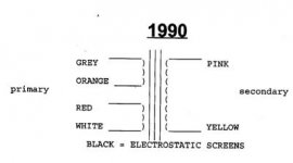
Pic1: Schematics from Lundahl

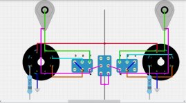
Pic 2: My 1:8/1:16 switch (this only shows schematics for the switch). The numbers in the switch are showing the corresponding pin on the transformer that it is wired to and not the pin number on the switch itself.

Pic 3: SUT bypass schematics. "In" on SUT is pimary coils and "Out" is secondary coils. Secondary coil is within the active circuit in bypass mode. Bad idea?

I am about to build an EAR834p MM phonostage clone (with upgraded components) and also building a MC SUT made of two Lundahl LL1931 step up transformers. The idea is to put all of this into one enclosure. In the future I might expand this with a tube preamp part as well for DAC, CD etc but for now I will use my Vincent SA-T8 preamp and hook up my phonostage to it.
I have a lot of DIY inspiration and energy, but less actual knowledge. I have done a lot of DIY in other areas (speakers, boats, etc) but my knowledge in electronics is basic at best so be kind and gentle. 🙂
I understand the schematics on how to wire the SUT and connect it to the EAR834p but I would like to have two modifications that I would like some pros (you guys) to look at and guide me so I do not mess things up. I recently bought a used Rega P6 turntable with a Clearaudio Essence MC, hence the need of a SUT and a phonostage.
The two modifications I would like to implement are:
1. A switch for switching between the LL1931 two step up options 1:8 and 1:16. I made a schematic with a 4PDT switch that I think would work but perhaps I made a mistake. Please double check for me. 🙂 Pictures below.
2. I would also like to have a switch that can easily bypass the SUT in case I would like to use a MM pickup. I have made a schematic using another 4PDT switch that might work. However, during bypass mode, the circuit is still connected to the SUTs secondary coil. Don't know if this might be a problem (extra resistance perhaps?)? Please look at it and comment and give advice if needed. 🙂
Pic1: Schematics from Lundahl
Pic 2: My 1:8/1:16 switch (this only shows schematics for the switch). The numbers in the switch are showing the corresponding pin on the transformer that it is wired to and not the pin number on the switch itself.
Pic 3: SUT bypass schematics. "In" on SUT is pimary coils and "Out" is secondary coils. Secondary coil is within the active circuit in bypass mode. Bad idea?
Last edited:
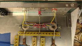
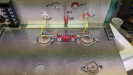
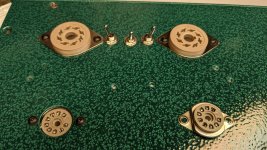
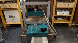
I built a tube phonostage and used octal based Sowter SUTs wired so they could be plugged into the top plate from the outside. (see last picture) I thought it would be quieter than having a SUT connected by a set of interconnects. Not so I found. At some point I pulled the octal based SUTs and built some jumpers with socket plugs and wired to jump the sockets in order to try a stand alone SUT. I found that with minor repositioning, I could get the background noise level much quieter than I ever could with the built in SUTs. Crazy
Attachments
My idea is to use a "full size" enclosure with internal metal walls between phono stage, SUT and Power supply. Hopefully that will take care of that problem. I will however make a mockup first and listen for noise. Do you have any input regarding my questions about the two switches?

Well, mine had it's power supply six feet away so that wasn't a factor. The ability to move the SUTs turned out to be helpful, even an inch or two could make a huge difference I found. I thought I had done a good thing only to be proved wrong. I do not have an expert opinion on your switches/schematics as I am far from an expert. Here is how I ended up wiring the SUTs I just jump them externally if I need to bypass them.
Attachments
Not such a good idea to have all that wiring and the switches before the phono inputs,
where the signal levels are extremely low. I would rather have two separate phono stages,
one MC and one MM, before doing that.
where the signal levels are extremely low. I would rather have two separate phono stages,
one MC and one MM, before doing that.
Yes, under different circumstances that would be ideal. However, the MM stages I built (I built two for different TTs) are next to silent with a separate SUT and well shielded interconnects. Much quieter than I expected!
If you've got a schematic for a stand alone all tube MC phonostage I'd love to see it @rayma .
If you've got a schematic for a stand alone all tube MC phonostage I'd love to see it @rayma .
Tubes would not be a low noise solution for MC (which is why there are SUTs),
but shielding is very important. Verion/Cotter used triaxial cables with their SUT.
but shielding is very important. Verion/Cotter used triaxial cables with their SUT.
For my interconnects from the SUT to the phono I had nice results with Mogami 2549 soldered to some Pro-Fi Neutrik RCAs. Shield attached to one end only. Surprisingly silent.
Hi, Depending on your MC cart the EAR clone has enough gain to fun a MC without SUT. I did it with a 103 which has a 0.3mv output. All you need to do is to change the 47K resistor for the appropriate one for your MC.
Cheers
Cheers
I built a similar preamp, the difference is the inclusion of a line stage with tone controls (Baxandall).
I didn't use PCB's if you don't solder point to point, to the EAR834 I included some Lundalh LL9226 for MC.
To select the input source I used a 4 pole 6 position rotary selector, that way I have 1 MC input, 2 MM inputs and 3 line inputs.
I have the lundalh wired for 1:10 gain and its load resistance for 0.3mV capsules.
Regarding the previous comment, a DL103 will not work well on a MM input, even with a boost of 1:10 (apparently ideal) it will not adjust the frequency response well if a load resistor is not installed according to its impedance.
I didn't think about that. If this solution compromises sound quality and noise level I will get rid of the switches. I don't think I will change cartridge that often, but flexibility is nice though. However, one version of the original EAR834P had a MM/MC switch and a built in SUT, and also some high end SUTs have switches for different gains and impedances, but certainly better implemented than my idea I suppose. I have seen som DIY PCB boards with a switch for different gain that probably have a much shorter signal path than my idea. This one example: https://www.diyaudio.com/community/threads/lundahl-ll1931ag-stepup-transformer.379447/Not such a good idea to have all that wiring and the switches before the phono inputs,
where the signal levels are extremely low. I would rather have two separate phono stages,
one MC and one MM, before doing that.
However, these are sold as a kit from the states. I live in Sweden and Lundahl is a Swedish company so from an economical perspective it doesn't make sense to import the kit from overseas with taxes, shipping, customs etc instead of buying the step ups directly from Lundahl here in Sweden.
I could insert two inputs, one for MM and the other for MC and move the wires inside if needed in the future.
Last edited:
I have a Clearaudio Essence MC. 0.4mV, 11 Ohms. I know thee EAR has a lot of gain (too much some people think) but I have read that increasing the gain with a SUT is much better since it creates much less noise. I think I rather use a SUT and install a volume knob.Hi, Depending on your MC cart the EAR clone has enough gain to fun a MC without SUT. I did it with a 103 which has a 0.3mv output. All you need to do is to change the 47K resistor for the appropriate one for your MC.
Cheers
I use Mogami 2549 for all interconnects as well. 🙂For my interconnects from the SUT to the phono I had nice results with Mogami 2549 soldered to some Pro-Fi Neutrik RCAs. Shield attached to one end only. Surprisingly silent.
As I wrote in the first post I might go that route myself later on. I guess your line stage was passive? Perhaps I go with a rotary selector. That's actually a really good idea. Then I can expand this project in the future and include a preamp section for my DAC as well, and volume control. 🙂I built a similar preamp, the difference is the inclusion of a line stage with tone controls (Baxandall).
I didn't use PCB's if you don't solder point to point, to the EAR834 I included some Lundalh LL9226 for MC.
To select the input source I used a 4 pole 6 position rotary selector, that way I have 1 MC input, 2 MM inputs and 3 line inputs.
I have the lundalh wired for 1:10 gain and its load resistance for 0.3mV capsules.
Regarding the previous comment, a DL103 will not work well on a MM input, even with a boost of 1:10 (apparently ideal) it will not adjust the frequency response well if a load resistor is not installed according to its impedance.
I am a little confused though on how you wired that setup? How did you bypass the SUT in MM mode? Did you use separate phono stages for MM and MC? I can see that if you put the phono stage on the output side of the selector then one input would go directly to output and one trough the SUT, but then all the inputs would go to the phono stage. I guess this in not how you did it since you have 3 line inputs too? But if the 834 is between the input side and the selector, then I can't se how you bypass the SUT without a switch anyway. I hope what I say makes sense. 🙂
Last edited:
Hello
I have 3 sets of RCA inputs (1MC and 2 MM).
Next to one of them are placed the Lundalh.
Now the three signal inputs (2 from RCA MM and 1 from SUT output) go to the rotary selector.
After the selector, the selected input goes to the EAR834 phono stage.
Sorry if I don't explain well.
I have 3 sets of RCA inputs (1MC and 2 MM).
Next to one of them are placed the Lundalh.
Now the three signal inputs (2 from RCA MM and 1 from SUT output) go to the rotary selector.
After the selector, the selected input goes to the EAR834 phono stage.
Sorry if I don't explain well.
Ok, then I understand. I thought you used six inputs and three of them was not routed to the phono stage. 🙂
I have looked around on the net some more and found that for the most part people (and commercial products) then to have separate inputs for MM and MC and route both of them to a switch where one goes directly to the phono stage and the other have the SUT directly after input and then goes to the switch and then to the phono stage. I think that is how I will do it. 🙂
I have looked around on the net some more and found that for the most part people (and commercial products) then to have separate inputs for MM and MC and route both of them to a switch where one goes directly to the phono stage and the other have the SUT directly after input and then goes to the switch and then to the phono stage. I think that is how I will do it. 🙂
- Home
- Amplifiers
- Tubes / Valves
- Phono stage build with SUT (need some help)